+86 512 68781993


Introduction to PID Diagram Knowledge of Valve Industry
PID diagram is the technical core of factory production. Whether it is an engineer from a design institute, an electrical technician, or a main operator of the central control room, understand the meaning of each letter and symbol on the PID diagram, and clearly understand the meaning of these components Functions and control methods are essential skills as an electrician.
1. What is PID diagram?
Flow chart:
That is, Process Flow Diagram , or PFD for short , is completed by the process professional. It contains the main information of the entire device, operating conditions (temperature, pressure, flow, etc.), material balance (the nature of each logistics point, flow, operating conditions, etc.) Expressed in the logistics table), heat balance (heat load, etc.), design calculation (equipment size, heat transfer area, pump flow, etc.), main control points and control plans, etc.
Only one device with the same function and the same specification needs to be drawn.
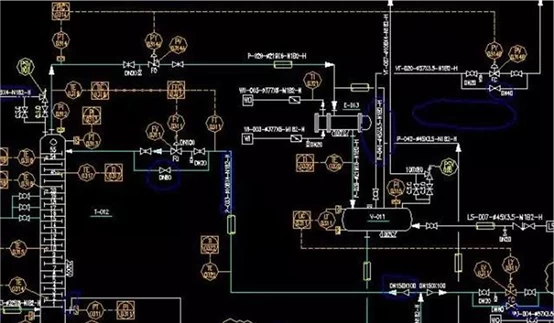
Process pipeline and instrument flow chart:
Namely Piping Instrument Diagram, or PID for short . PID is based on PFD, and is jointly completed by technology, pipeline installation and automatic control.
It is necessary to draw all the equipment, meters, pipes and their specifications, insulation thickness, etc., which is the main basis for drawing the pipeline layout.
The first version of the PID diagram is formed in the process package stage. With the deepening of the design stage, it is continuously supplemented and improved. It is published in stages and editions.
The publication of each edition of PID shows the progress of engineering design, and provides timely design information at the corresponding stage for technology, automation, equipment, electrical, telecommunications, piping, pipe machines, pipe materials, equipment layout, and water supply and drainage.
PID is one of the main products in basic design and detailed design. It reflects the comprehensive results of process design flow, equipment design, equipment and piping layout design, and automatic control instrument design.
2. What can the PID diagram tell us?
1. Use the specified categories of graphic symbols and text codes:
All equipment, machinery and driving machines that represent the process of the device, including spare equipment that needs to be in place and mobile equipment for production, are numbered and marked.
2. Use prescribed graphic symbols and text codes:
Indicate in detail all required pipes, valves(such as High pressure seal check valve), main pipe fittings (including temporary pipes, valves and pipe fittings), utility stations and insulation, etc. , and carry out numbering and marking.
3. Use the specified graphic symbols and words to substitute
Indicate all instruments with detection, indication and control functions , including disposable instruments and sensors, and are numbered and marked.
4. Use prescribed graphic symbols and text codes:
It indicates all sampling points for process analysis , and they are numbered and marked.
5. Matters that need to be explained on the map for safe production, test runs, starting and stopping, and accident handling:
Including the design requirements and key design dimensions of the process system for related disciplines such as automation and piping .
prompt:
PID diagram is also called process flow chart with control points.
With the help of unified graphical symbols and text codes, all the equipment, instruments, pipelines, valves and main pipe fittings required to establish petrochemical process installations according to their respective functions are used to meet the process requirements and safety and economy. Under the premise of the combination, to play a role in describing the structure and function of the process device.
Therefore, it is not only the basis for design and construction, but also a part of the complete technical data required for various aspects of enterprise management, trial operation, operation, maintenance, and start-up and shutdown.
Through the process pipeline and instrument flow chart, we can understand:
The number, name and tag of the equipment.
The technological process of the main materials.
Process flow of other materials.
Through the analysis of valves and control points, understand the control of the production process
3. Four major elements of PID design
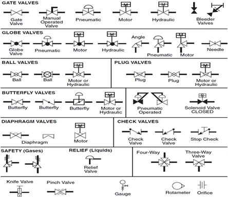
The process flow chart (PID) includes all the elements that the process needs to show. FIG PID most important four major elements: equipment, pipe lines, valves, gauges .
Below is the valve PID symbols