 86 512 68781993


Valve inspection and installation
Inspection before valve installation
① Carefully check and check whether the valve model and specification meet the requirements of the drawing.
② Check whether the valve stem and valve disc are flexible to open, and whether there is jamming or skewing.
③ Check whether the valve is damaged, and whether the thread of the threaded valve is correct and complete.
④ Check whether the combination of the valve seat and the valve body is firm, the connection between the valve disc and the valve seat, the valve cover and the valve body, and the valve stem and the valve disc.
⑤ Check whether the valve gasket, packing and fasteners (bolts) are suitable for the requirements of the working medium.
⑥ The old or long-standing pressure relief valve should be dismantled, and the dust, sand and other debris should be cleaned with water.
⑦Remove the port cover, check the sealing degree, and the valve disc must be closed tightly.
Pressione test of valve
Bassa pressione, medium-pressure and high-pressure valves should be subjected to strength test and tightness test, and alloy steel valves should also be subjected to spectral analysis of the shell one by one, and the material should be reviewed.
1. Strength test of valve
Il strength test of the valve is to test the valve in the open state to check the leakage on the outer surface of the valve. For valves with PN≤32MPa, the test pressure is 1.5 times the nominal pressure, the test time is not less than 5min, and there is no leakage at the shell and packing gland to be qualified.
2. Tightness test of valve
Il test is carried out with the valve completely closed to check whether there is leakage on the sealing surface of the valve. The test pressure, except for the butterfly valve, check valve, bottom valve and throttle valve, should generally be carried out at the nominal pressure. When the working pressure is used, it can also be tested with 1.25 times the working pressure, and it is qualified if the sealing surface of the valve disc does not leak.
Generale requirements for valve installation
1. The installation position of the valve should not hinder the operation, disassembly and maintenance of the equipment, the pipeline and the valve body itself, and at the same time, the appearance of the assembly should be considerato.
2. For valves on horizontal pipelines, the valve stem should be installed upwards, or installed at a certain angle, and the handwheel should not be installed downwards. The valve, valve stem and handwheel on the high-altitude pipeline can be installed horizontally, and the opening and closing of the valve can be remotely controlled by the chain at the low vertical position.
3. The arrangement is symmetrical, neat and beautiful; the valve on the riser, if the process allows, the valve handwheel is most suitable for operation at chest height, generally 1.0-1.2m from the ground, and the valve stem must follow the operator. installation direction.
4. For the valves on the side-by-side risers, the elevation of the center line should be the same, and the clear distance between the handwheels should not be less than 100mm; the valves on the side-by-side horizontal pipes should be staggered to reduce the distance between the pipes.
5. When installing heavy valves on water pumps, heat exchangers and other equipment, valve brackets should be installed; when valves are frequently operated and installed at a distance of more than 1.8m from the operating surface, a fixed operating platform should be installed.
6. If there is an arrow mark on the valve body of the valve, the direction of the arrow is the flow direction of the medium. When installing the valve, care should be taken to make the arrow point in the same direction as the medium in the pipeline.
7. When installing flanged valves, ensure that the end faces of the two flanges are parallel and concentric with each other, and double gaskets are not permesso.
8. When installing a threaded valve, one threaded valve should be equipped with a union to facilitate disassembly. The setting of the union should consider the convenience of maintenance. Usually, the water flows through the valve first and then the union.
Valvola Installation Precautions
1. The valve body material is mostly made of cast iron, which is brittle, so it should not be hit by heavy objects.
2. When handling the valve, it is not allowed to throw it at will; quando lifting and hoisting the valve, the rope should be tied to the valve body, and it is strictly forbidden to be tied to the handwheel, valve stem and flange fori dei bulloni.
3. The valve should be installed in the most convenient place for operation, maintenance and repair, and it is strictly forbidden to bury it in the ground. For the valves on the pipelines in direct burial and trenches, an inspection well room should be set up to facilitate the opening, closing and adjustment of the valves.
4. Ensure that the thread is intact, and wrap hemp, lead oil or PTFE raw material tape on the thread. When twisting, use a wrench to clamp the hexagonal valve body screwed into one end of the pipe.
5. When installing the flanged valve, pay attention to tighten the connecting bolts diagonally, and use even force when screwing, to prevent the gasket from running off or causing deformation and damage to the valve body.
6. The valve should be kept closed during installation. For threaded valves close to the wall, it is often necessary to remove the valve stem, valve disc and handwheel during installation before they can be avvitato. When disassembling, turn the handwheel to keep the valve open before disassembling.
Installazione of common valves
Installazione of gate valve, globe valve and check valve
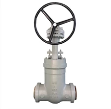
Cancello valve, also known as gate valve, is a valve that uses a gate to control the opening and closing, and adjusts the pipeline flow and opens and closes the pipeline by changing the cross section. Gate valves are mostly used for pipelines that fully open or fully close the fluid medium. Gate valve installation generally has no directional requirements, but it cannot be flipped.
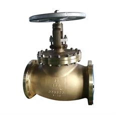
C95800 globe valve
The globe valve is a valve that uses the valve disc to control the opening and closing. Aggiusta il medium flow or cut off the medium passage by changing the gap between the valve disc and the valve seat, that is, changing the size of the channel section. quando installing the shut-off valve, attention must be paid to the flow direction of the fluid.
Il principle that must be followed when installing the globe valve is that the fluid in the pipeline passes through the valve hole from bottom to top, commonly known as "low in and high out", and it is not allowed to install it in reverse.
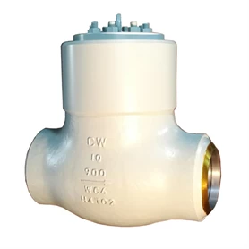
Pressure check valve
Check valve, also known as check valve and one-way valve, is a valve that automatically opens and closes under the action of the pressure difference between the front and rear of the valve. Secondo their different structures, check valves include lift type, swing type and butterfly wafer type. Lift check valve is divided into horizontal and verticale. When installing the check valve, attention should also be paid to the flow direction of the medium and cannot be installed in reverse.
Installazione of pressure reducing valve
Il pressure reducing valve is a valve that reduces the inlet pressure to a certain required outlet pressure through adjustment, and relies on the energy of the medium itself to automatically keep the outlet pressure stable.
A partire dal the point of view of fluid mechanics, the pressure reducing valve is a throttling element whose local resistance can be changed, that is, by changing the throttling area, the flow rate and the kinetic energy of the fluid are changed, resulting in different pressure losses, so as to achieve the purpose of pressure reduction. Quindi rely on the adjustment of the control and adjustment system to balance the fluctuation of the pressure behind the valve with the spring force, so that the pressure behind the valve remains constant within a certain error range.
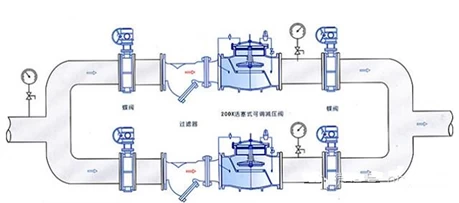
Installazione of pressure reducing valve
1. The pressure relief valve group installed vertically is generally installed along the wall at a suitable height from the ground; la pressione relief valve group installed horizontally is generally installed on the permanent operating platform.
2. The application steel is loaded into the wall on the outside of the two control valves (usually used for globe valves) to form a bracket, and the bypass pipe is also stuck on the bracket to level and align.
3. The pressure reducing valve should be installed upright on the horizontal pipeline, and should not be inclined. The arrow on the valve body should point to the direction of medium flow, and should not be installed backwards.
4. Globe valves and high and low pressure pressure gauges should be installed on both sides to observe the pressure changes before and after the valvola. The diameter of the pipeline behind the pressure reducing valve should be 2#-3# larger than the inlet pipe diameter before the valve, and a bypass pipe should be installed for maintenance.
5. The pressure equalizing pipe of the membrane pressure reducing valve should be connected to the low pressure pipeline. Low-pressure pipelines should be equipped with safety valves to ensure the safe operation of the system.
6. When used for steam decompression, a drain pipe should be set. For pipeline systems that require a higher degree of purification, a filter should be installed before the pressure reducing valve.
7. After the installation of the pressure reducing valve group, the pressure reducing valve and safety valve should be pressure tested, flushed and adjusted according to the design requirements, and the adjusted mark should be made.
8. When flushing the pressure reducing valve, close the inlet valve of the pressure reducer and open the flushing valve for flushing.
Installazione of traps
Il basic function of the steam trap is to discharge the condensed water, air and carbon dioxide gas in the steam system as soon as possible; allo stesso tempo, it automatically prevents the leakage of steam to the greatest extent. There are many types of traps, each with different performance.
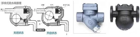
Dipendente on the working principle of the trap, it can be divided into the following three types:
Meccanico type: The action depends on the change of the condensate level in the steam trap, including:
Galleggiante type: The float is a closed hollow sphere.
Open-up float type: The float is a barrel type with an upward opening.
Aprire verso il basso Float Type: The float is a barrel type with an opening down.
Thermostatic: Acts on changes in liquid temperature, including:
Bimetal: The sensitive element is a bimetal.
Vapore pressure type: The sensitive element is a bellows or an ink cartridge, which is filled with volatile liquid.
Termodinamico type: The action depends on the change of the thermodynamic properties of the liquido.
Disco type: Due to the different flow rates of liquid and gas under the same pressure, the different dynamic and static pressures generated drive the disc valve to act.
Pulse type: When the condensate of different temperatures passes through the two-pole orifice plates in series, different pressures will be formed between the two-pole orifice plates, driving the valve disc to act.
Installazione of traps
1. Shut-off valves (shut-off valves) should be set before and after, and a filter should be set between the trap and the front shut-off valve to prevent dirt from condensing water from clogging the trap.
2. An inspection pipe should be installed between the trap and the rear shut-off valve to check whether the trap works normally. If a large amount of steam is emitted when the inspection pipe is opened, it means that the trap is broken and needs to be repaired.
3. The purpose of setting the bypass pipe is to discharge a large amount of condensed water during startup and reduce the drainage load of the trap.
4. When the steam trap is used to drain the condensed water of the heating equipment, it should be installed at the lower part of the heating equipment, so that the condensate pipe is vertically returned to the steam trap to prevent the water from being stored in the heating equipment.
5. The installation location should be as close to the drainage point as possibile. If the distance is too far, air or steam will accumulate in the slender pipe in front of the trap.
6. When the horizontal pipeline of the steam main pipe is too long, the drainage problem should be considered.
Installation of safety valve
Il safety valve is a special valve that the opening and closing parts are in a normally closed state under the action of external force. When the pressure of the medium in the equipment or pipeline rises beyond the specified value, it discharges the medium to the outside of the system to prevent the medium pressure in the pipeline or equipment from exceeding the specified value. .
Sicurezza valves are automatic valves, mainly used in boilers, pressure vessels and pipelines. The control pressure does not exceed the specified value, which plays an important role in protecting personal safety and equipment operation. NOTE The safety valve must be pressure tested before it can be used.
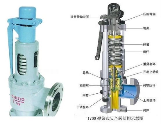
1. Before installation, the product must be carefully inspected to verify whether there is a certificate of conformity and product manual to clarify the constant pressure when leaving the factory.
2. The safety valve should be arranged as close to the platform as possible for inspection and maintenance.
3. The safety valve should be installed vertically, the medium should flow out from bottom to top, and the verticality of the valve stem should be controllato.
4. Under normal circumstances, shut-off valves cannot be set before and after the safety valve to ensure safety and reliability.
5. Safety valve pressure relief: when the medium is liquid, it is generally discharged into the pipeline or closed system; when the medium is gas, it is generally discharged to the outdoor atmosphere;
6. The oil and gas medium can generally be discharged into the atmosphere. The outlet of the safety valve vent pipe should be 3m higher than the highest surrounding structures, but the following conditions should be discharged into a closed system to ensure safety.
7. The diameter of the population pipe should be at least equal to the inlet pipe diameter of the valve; the diameter of the discharge pipe should not be smaller than the outlet diameter of the valve. The discharge pipe should be led to the outside and installed with an elbow, so that the pipe outlet faces a area sicura.
8. When the safety valve is installed, when the connection between the safety valve and the equipment and pipeline is opening welding, the opening diameter should be the same as the nominal diameter of the safety valve.
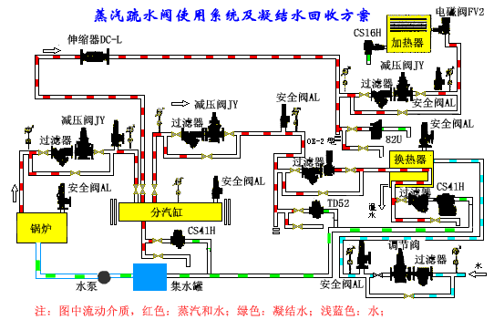
Centralized application of steam trap system
Common valve failures and causes
1. Causes and maintenance methods of stuffing box leakage
|
causa of issue |
Manutenzione metodo |
|
Il filling method is incorrect (for example, the whole root is placed in a spirale) |
Corretta Imballaggio |
|
Valve stem is deformed or corroded and rusted |
Repair or replace |
|
Filler aging |
Replace packing |
|
Improprio or excessive force |
Lento opening and closing, smooth operation |
2. Reasons for valve stem failure and maintenance methods
|
causa of issue |
Manutenzione metodo |
|
Stem damage, corrosion tripping |
Replace valve |
|
valve stem bending |
When the valve is not easy to open, do not use a long tool to pry off the handwheel, the twisted valve stem needs to be replaced |
|
Stem nut tilt |
Replace valve or valve |
|
aprire air valve rusted |
All'aperto valve should be strengthened maintenance, turn the handwheel regularly |
3. Causes and maintenance methods of sealing surface leakage
|
cause of issue |
Maintenance method |
|
The sealing surface is worn and slightly corroded |
Grind regularly |
|
Improper closing, poor sealing surface contact |
Slowly and repeatedly open and close several times |
|
The valve stem is bent, and the upper and lower sealing surfaces are not on the center line |
repair or replace |
|
Impurities block valve holes |
Open, remove debris, then close slowly, add a filter if necessary |
|
The sealing ring is not tightly matched with the valve seat and valve disc |
riparazione |
|
The valve disc and the valve stem are not firmly connected |
Repair or replacement |
4. Other faults, causes and maintenance methods
|
Guasto |
cause of issue |
Maintenance method |
|
Gasket leak |
The gasket material is not suitable or is affected by the medium in daily use and fails |
Use gaskets suitable for working conditions or replace gaskets |
|
Cracked valve |
Frost damage or excessive force when installing threaded valves |
Heat preservation and antifreeze, even and appropriate force during installation |
|
Damaged handwheel |
Heavy objects hit, the long rod is not opened by prying, the inner square hole is worn and chamfered |
Avoid impact, use even force when opening, correct direction, file square hole or replace handwheel |
|
Gland break |
Uneven force when pressing il coperchio |
Tighten nuts symmetrically |
|
Gate failure |
The wedge gate is not closed tightly due to corrosion, and the top wedge of the double gate is danneggiato |
Periodically ground and replaced with carbon steel top wedges |
Common faults and causes of automatic valves
1. Common faults, causes, prevention and maintenance of check valves
|
Guasto |
cause of issue |
Maintenance method |
|
medium backflow |
1. The sealing surface between the valve core and the valve seat is danneggiato 2. There is dirt between the valve core and valve seat |
1. Grinding the sealing surface 2. Remove dirt |
|
Spool does not open |
1. The sealing surface is stuck by scale 2. The shaft is rusted |
1. Remove scale 2. Grind the rust to make it flexible |
|
Disc is broken |
The pressure of the medium before and after the valve is in a nearly balanced "tug-saw" state, which makes the valve disc made of brittle material beat frequently |
Using ductile material disc |
2. Common faults, causes, prevention and repair of traps
|
Guasto |
cause of issue |
Maintenance method |
|
undrained |
1. The steam pressure is too low 2. Steam and condensate do not enter the trap 3. The pontoon-type pontoon is too light 4. The valve stem of the float type is stuck with the casing 5. The valve hole or channel is blocked 6. The thermostatic valve core is broken, blocking the valve hole |
1. Adjust the steam pressure 2. Check whether the steam pipeline valve is closed and blocked 3. Appropriately increase the amount or replace the buoy 4. Overhaul or replacement to make it flexible 5. Remove the clogging debris, install a filter in front of the valve 6. Replace the valve core |
|
scarico |
1. The valve core and valve seat are worn, and steam leaks 2. The drain hole cannot be closed by itself 3. The buoy-type buoy is small in size and cannot float |
1. Grinding the sealing surface 2. Check whether there is dirt blockage 3. Properly increase the volume of the buoy |
|
Continuous operating temperature drop |
1. The drainage volume is lower than the amount of condensed water 2. The amount of condensed water in the pipeline increases |
1. Replace the appropriate trap 2. Install steam trap |
3. Common faults, causes, prevention and maintenance of pressure reducing valves
|
Guasto |
cause of issue |
Maintenance method |
|
Unstable pressure behind valvola |
1. The pulse type is the improper selection of the valve diameter, and the pressure difference between the two ends of the medium is large. 2. Improper selection of spring-type adjustment springs |
1. Replace the appropriate pressure reducing valve 2. Replace the appropriate adjusting spring |
|
The valve is blocked |
1. The control channel is blocked by debris 2. The rust in the piston is stuck and cannot be moved down at the highest posizione |
1. Remove sundries and install a filter in front of the valve 2. Overhaul the piston to make it flexible |
|
valve straight |
1. The piston is stuck in a certain position 2. The lower spring of the main valve disc is broken 3. The valve handle of the pulse valve is stuck at the tight position 4. There is dirt stuck or severe corrosion between the main valve disc and the sealing surface of the valve seat 5. Film failure |
1. Overhaul the piston to make it flexible 2. Replace the spring 3. Overhaul to make it flexible 4. Rimuovere lo sporco e macinare regolarmente la superficie di tenuta 5. Sostituire il film |
|
La pressione dietro il La valvola non può essere regolata |
1. La molla di regolazione fallisce 2. Il cappuccio perde e non può mantenere la pressione 3. Pistone, usura del cilindro o corrosione 4. Il corpo della valvola è riempito con acqua condensata |
1. Sostituire la molla di regolazione 2. Manutenzione tempestiva e sostituzione delle guarnizioni 3. Revisionare il cilindro e sostituire l'anello del pistone 4. Allentare la spina e scaricare l'acqua condensata |
4. Guasti comuni, cause, prevenzione e riparazione delle valvole di sicurezza
|
Guasto |
Causa del problema |
Metodo di manutenzione |
|
Perdita di superficie di sigillatura |
1. C'è sporco o usura sulla superficie di tenuta del nucleo della valvola e sedile della valvola 2. La linea centrale dello stelo della valvola non è corretta |
1. Rimuovere lo sporco o macinare il sigillo 2. Correggere la linea centrale dello stelo della valvola di raddrizzamento |
|
La pressione di lavoro eccessiva fa non aperto |
1. La leva è bloccata o il perno è arrugginito 2. Il peso di tipo leva viene spostato 3. La molla a molla viene deformata o fallisce a causa del calore 4. Il nucleo della valvola e il sedile della valvola sono bloccati |
1. Leva o pin di revisione 2. Regolare la posizione del martello pesante 3. Sostituire la molla 4. Test di scarico regolare |
|
Accendi senza lavorare pressione |
1. Il peso della leva si muove verso l'interno 2. L'elasticità della primavera non è sufficiente |
1. Regolare la posizione del martello pesante 2. Stringere o sostituire la molla |
|
La bobina non si chiude automaticamente dopo l'apertura |
1. Deflessione della leva 2. Piegamento primaverile di tipo primaverile 3. Il nucleo della valvola o lo stelo della valvola non è corretto |
1. Leva di revisione 2. Regolare la molla 3. Regolare il nucleo della valvola o lo stelo della valvola |
Manutenzione della valvola comune
Durante l'installazione e l'uso del valvola, per ragioni come la qualità e l'usura della produzione, la valvola è soggetto a perdite e chiusura lassista.
1. Riparazione di perdite della ghiandola
(1) Riparazione di perdite di copertura della valvola piccola
(2) Riparazione di perdite della ghiandola della valvola più grande
2. Non può aprirsi o aprirsi senza vapore o acqua
(1) valvola del gate
(2) Valvola globale
(3) Blocco della valvola o della tubazione
3. Non posso Spegnere o chiudere
(1) La valvola non è chiusa strettamente: può essere dovuta allo sporco bloccato tra la sede della valvola e il nucleo della valvola o la valvola Il sedile e il nucleo della valvola sono graffiati, in modo che la valvola non possa essere chiusa strettamente.
(2) Impossibile chiudere: quando la valvola è aperta, la forza è troppo forte e La testa è aperta.