 86 512 68781993


Ventilprüfung und Installation
Inspektion Vor der Ventilinstallation
① Überprüfen Sie sorgfältig und prüfen Sie, ob das Ventilmodell und die Spezifikation sich treffen die Anforderungen der Zeichnung.
② Überprüfen Sie, ob der Ventilstamm und die Ventilscheibe flexibel zu öffnen sind und ob Es gibt Jamming oder Schub.
③ Überprüfen Sie, ob das Ventil beschädigt ist und ob der Faden des Das Gewindeventil ist korrekt und vollständig.
④ Überprüfen Sie, ob die Kombination des Ventilsitzes und der Ventilkörper ist fest, die Verbindung zwischen der Ventilscheibe und dem Ventilsitz, der Ventilabdeckung und der Ventilkörper und der Ventilstamm und die Ventilscheibe.
⑤ Überprüfen Sie, ob die Ventildichtung, die Verpackung und die Verschlüsse (Schrauben) sind Geeignet für die Anforderungen des Arbeitsmediums.
⑥ Das alte oder langjährige Druckentlastungsventil sollte abgebaut werden und Staub, Sand und andere Trümmer sollten mit Wasser gereinigt werden.
⑦Removieren Sie die Anschlussabdeckung, überprüfen Sie den Dichtungsabschluss und die Ventilscheibe muss sein fest geschlossen.
Druck Ventilprüfung
Niedriger Druck, Mitteldruck- und Hochdruckventile sollten einem Festigkeitstest ausgesetzt werden und Dichtheitstest und Legierungsstahlventile sollten ebenfalls spektral unterzogen werden Analyse der Shell nacheinander und das Material sollte überprüft werden.
1. Festigkeitstest des Ventils
Das Der Festigkeitstest des Ventils besteht darin, das Ventil im offenen Zustand zu testen, um die zu überprüfen Leckage auf der Außenfläche des Ventils. Für Ventile mit PN ≤ 32MPA den Testdruck ist das 1,5 -fache des Nenndrucks, die Testzeit beträgt mindestens 5 min, und Es gibt keine Leckage an der Hülle und der Packdrüse, die qualifiziert werden müssen.
2. Dichtungstest des Ventils
Das Der Test wird mit vollständig geschlossenem Ventil durchgeführt, um zu prüfen, ob es vorhanden ist Leckage auf der Dichtfläche des Ventils. Der Testdruck außer dem Schmetterlingsventil, Scheckventil, Bodenventil und Drosselklappenventil sollte im Allgemeinen im Nenndruck ausgeführt werden. Wenn der Arbeitsdruck verwendet wird, ist es kann auch mit dem 1,25 -fachen des Arbeitsdrucks getestet werden, und es ist qualifiziert, wenn Die Dichtfläche der Ventilscheibe läuft nicht.
Allgemein Anforderungen für die Installation der Ventile
1. Die Installationsposition des Ventils sollte den Betrieb nicht behindern. Demontage und Wartung der Ausrüstung, der Rohrleitung und des Ventilkörpers sich selbst und gleichzeitig das Erscheinungsbild der Baugruppe sein betrachtet.
2. Für Ventile auf horizontalen Rohrleitungen sollte der Ventilstamm nach oben installiert werden. oder in einem bestimmten Winkel installiert, und das Handrad sollte nicht installiert werden nach unten. Das Ventil, Ventilstamm und Handrad an der hochligen Pipeline kann horizontal installiert werden und die Das Öffnen und Schließen des Ventils kann von der Kette an der Kette remote gesteuert werden niedrige vertikale Position.
3. Die Anordnung ist symmetrisch, ordentlich und schön; das Ventil am Riser, wenn der Prozess es zulässt, ist das Ventilhandrad am besten geeignet für Betrieb in Brusthöhe, im Allgemeinen 1,0-1,2 m vom Boden und das Ventil STEM muss dem Bediener folgen. Installationsrichtung.
4. Für die Ventile an den Side-by-Side-Aufstiegshöhen der Mitte Die Linie sollte gleich sein, und der klare Abstand zwischen den Handrädern sollte nicht weniger als 100 mm; Die Ventile an den horizontalen Rohren nebeneinander sollten Seien Sie gestaffelt, um den Abstand zwischen den Rohren zu verringern.
5. Bei der Installation schwerer Ventile an Wasserpumpen, Wärmetauschern und anderen Geräte, Ventilhalterungen sollten installiert werden. Wenn Ventile häufig sind in einem Abstand von mehr als 1,8 m vom Betrieb betrieben und installiert Oberfläche sollte eine feste Betriebsplattform installiert werden.
6. Wenn sich eine Pfeilmarke am Ventilkörper des Ventils befindet, ist die Richtung des Pfeils ist die Strömungsrichtung des Mediums. Bei der Installation des Ventils sollte darauf geachtet werden, den Pfeilpunkt zu erreichen In die gleiche Richtung wie das Medium in der Pipeline.
7. Stellen Sie bei der Installation von Flanschventilen sicher, dass die Endgesichter der beiden Flansche sind parallel und konzentrisch miteinander und Doppeldichtungen nicht erlaubt.
8. Bei der Installation eines Gewindeventils sollte ein Gewindeventil ausgestattet sein mit einer Gewerkschaft, um die Demontage zu erleichtern. Die Einstellung der Gewerkschaft sollte die Bequemlichkeit der Wartung berücksichtigen. Normalerweise fließt das Wasser zuerst durch das Ventil und dann durch die Vereinigung.
Ventil Vorsichtsmaßnahmen für Installation
1. Das Ventilkörpermaterial besteht hauptsächlich aus Gusseisen, das so spröde ist Es sollte nicht von schweren Objekten getroffen werden.
2. Beim Umgang mit dem Ventil darf es es nicht nach Belieben werfen; Wenn Heben und Hebe des Ventils sollte das Seil an den Ventilkörper gebunden sein, und Es ist strengstens verboten, an das Handrad, den Ventilstamm und den Flansch gebunden zu sein Bolzenlöcher.
3. Das Ventil sollte an dem bequemsten Ort für den Betrieb installiert werden. Wartung und Reparatur, und es ist streng verboten, es im Boden zu begraben. Für die Ventile auf den Pipelines in direkter Bestattung und Gräben, an Inspektion gut Raum sollte eingerichtet werden, um die Öffnung, das Schließen zu erleichtern und Einstellung der Ventile.
4. Stellen Sie sicher, dass der Faden intakt ist, und wickeln Sie Hanf, Bleiöl oder PTFE RAW ein Materialband auf dem Faden. Verwenden Sie beim Drehen einen Schraubenschlüssel, um das sechseckige Sechseck zu klemmen Ventilkörper in ein Ende des Rohrs geschraubt.
5. Bei der Installation des Flanschventils achten Sie darauf, das zu verschärfen Anschließende Schrauben diagonal und wenden Sie beim Schrauben gleichmäßige Kraft an, um die zu verhindern Dichtung vom Ablauf oder Verformung und Beschädigung des Ventilkörpers.
6. Das Ventil sollte während der Installation geschlossen werden. Bei Gewindeventilen in der Nähe der Wand ist es häufig erforderlich, um zu entfernen Der Ventilstamm, die Ventilscheibe und das Handrad während der Installation, bevor sie sein können aufgeschmissen. Beim Zerlegen drehen Sie die Handrad, um das Ventil vor dem Zerlegen offen zu halten.
Installation von gemeinsamen Ventilen
Installation vom Ventil, des Globusventils und des Scheckventils
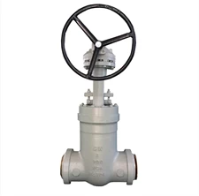
Tor Das Ventil, auch als Gate -Ventil bekannt, ist ein Ventil, das ein Gate zur Steuerung des Öffnen und Schließen und Anpassung des Pipeline -Flusses und öffnet und schließt die Pipeline durch Ändern des Querschnitts. Die Ventile werden hauptsächlich für Rohrleitungen verwendet, die das Flüssigkeitsmedium vollständig öffnen oder vollständig schließen. Die Installation der Gästeventile hat im Allgemeinen keine Richtungsanforderungen, sondern es kann nicht umgedreht werden.
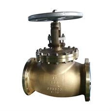
C95800 Durchgangsventil
Das Globusventil ist ein Ventil, das das verwendet Ventilscheibe zur Steuerung der Öffnung und Schließung. Verstelle die mittlerer Strömung oder schneiden Sie den mittleren Durchgang ab Durch Ändern der Lücke zwischen der Ventilscheibe und dem Ventilsitz, das heißt, Ändern der Größe des Kanalabschnitts. Wann Wenn Sie das Absperrventil installieren, muss die Flussrichtung von Aufmerksamkeit geschenkt werden die Flüssigkeit.
Das Prinzip, das bei der Installation des Globusventils befolgt werden muss, ist, dass die Flüssigkeit in der Rohrleitung verläuft durch das Ventilloch von unten nach oben, allgemein bekannt als "niedrig und hoch out", und es darf nicht erlaubt Installieren Sie es umgekehrt.
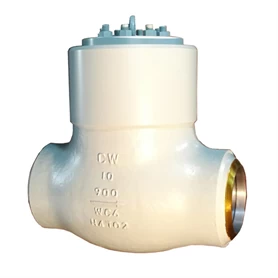
Druckprüfventil
Scheckventil, auch als Scheckventil und Einwegventil bezeichnet, ist IS IS Ein Ventil, das sich automatisch öffnet und schließt unter der Wirkung des Drucks Unterschied zwischen Vorder- und Rückseite des Ventils. Entsprechend Ihre verschiedenen Strukturen, Scheckventile umfassen Auftriebstyp, Schwungstyp und Schmetterlingswafertyp. Hubprüfventil ist in horizontal und unterteilt vertikal. Bei der Installation des Scheckventils sollte auch die Aufmerksamkeit an die Strömungsrichtung des Mediums bezahlt werden und kann nicht umgekehrt installiert werden.
Installation Ventil des Druckreduzierungsventils
Das Druckreduzierungventil ist ein Ventil, das den Einlassdruck auf einen bestimmten reduziert Erforderlicher Auslassdruck durch Einstellung und stützt sich auf die Energie der Medium selbst, um den Auslassdruck automatisch stabil zu halten.
Aus Der Standpunkt der Flüssigkeitsmechanik, das Druckreduzierungsventil ist a Drossungselement, dessen lokaler Widerstand geändert werden kann, dh durch Veränderung Der Drosselbereich, die Durchflussrate und die kinetische Energie der Flüssigkeit sind verändert und führt zu unterschiedlichen Druckverlusten, um den Zweck zu erreichen der Druckreduzierung. Dann verlassen Schwankung des Drucks hinter dem Ventil mit der Federkraft, so dass die pressure behind the valve remains constant within a certain error range.
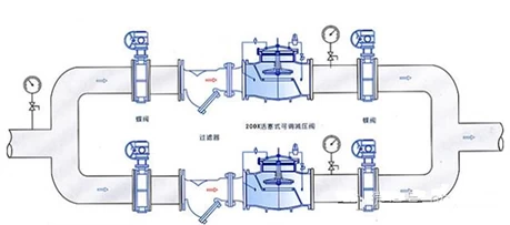
Installation Ventil des Druckreduzierungsventils
1. The pressure relief valve group installed vertically is generally installed along the wall at a suitable height from the ground; der Druck relief valve group installed horizontally is generally installed on the permanent operating platform.
2. The application steel is loaded into the wall on the outside of the two control valves (usually used for globe valves) to form a bracket, and the bypass pipe is also stuck on the bracket to level and align.
3. The pressure reducing valve should be installed upright on the horizontal pipeline, and should not be inclined. The arrow on the valve body should point to the direction of medium flow, and should not be installed backwards.
4. Globe valves and high and low pressure pressure gauges should be installed on both sides to observe the pressure changes before and after the Ventil. The diameter of the pipeline behind the pressure reducing valve should be 2#-3# larger than the inlet pipe diameter before the valve, and a bypass pipe should be installed for maintenance.
5. The pressure equalizing pipe of the membrane pressure reducing valve should be connected to the low pressure pipeline. Low-pressure pipelines should be equipped with safety valves to ensure the safe operation of the system.
6. When used for steam decompression, a drain pipe should be set. For pipeline systems that require a higher degree of purification, a filter should be installed before the pressure reducing valve.
7. After the installation of the pressure reducing valve group, the pressure reducing valve and safety valve should be pressure tested, flushed and adjusted according to the design requirements, and the adjusted mark should be made.
8. When flushing the pressure reducing valve, close the inlet valve of the pressure reducer and open the flushing valve for flushing.
Installation of traps
Das basic function of the steam trap is to discharge the condensed water, air and carbon dioxide gas in the steam system as soon as possible; zur selben Zeit, it automatically prevents the leakage of steam to the greatest extent. There are many types of traps, each with different performance.
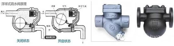
Abhängig on the working principle of the trap, it can be divided into the following three types:
Mechanisch type: The action depends on the change of the condensate level in the steam trap, including:
Schweben type: The float is a closed hollow sphere.
Aufmachen float type: The float is a barrel type with an upward opening.
Öffnen sich Float Type: The float is a barrel type with an opening down.
Thermostatic: Acts on changes in liquid temperature, including:
Bimetal: The sensitive element is a bimetal.
Dampf pressure type: The sensitive element is a bellows or an ink cartridge, which is filled with volatile liquid.
Thermodynamic type: The action depends on the change of the thermodynamic properties of the flüssig.
Rabatt type: Due to the different flow rates of liquid and gas under the same pressure, the different dynamic and static pressures generated drive the disc valve to act.
Impuls type: When the condensate of different temperatures passes through the two-pole orifice plates in series, different pressures will be formed between the two-pole orifice plates, driving the valve disc to act.
Installation of traps
1. Shut-off valves (shut-off valves) should be set before and after, and a filter should be set between the trap and the front shut-off valve to prevent dirt from condensing water from clogging the trap.
2. An inspection pipe should be installed between the trap and the rear shut-off valve to check whether the trap works normally. If a large amount of steam is emitted when the inspection pipe is opened, it means that the trap is broken and needs to be repaired.
3. The purpose of setting the bypass pipe is to discharge a large amount of condensed water during startup and reduce the drainage load of the trap.
4. When the steam trap is used to drain the condensed water of the heating equipment, it should be installed at the lower part of the heating equipment, so that the condensate pipe is vertically returned to the steam trap to prevent the water from being stored in the heating equipment.
5. The installation location should be as close to the drainage point as möglich. If the distance is too far, air or steam will accumulate in the slender pipe in front of the trap.
6. When the horizontal pipeline of the steam main pipe is too long, the drainage problem should be considered.
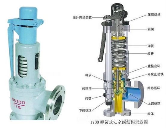
Installation of safety valve
Das safety valve is a special valve that the opening and closing parts are in a normally closed state under the action of external force. When the pressure of the medium in the equipment or pipeline rises beyond the specified value, it discharges the medium to the outside of the system to prevent the medium pressure in the pipeline or equipment from exceeding the specified value. .
Sicherheit valves are automatic valves, mainly used in boilers, pressure vessels and pipelines. The control pressure does not exceed the specified value, which plays an important role in protecting personal safety and equipment operation. NOTE The safety valve must be pressure tested before it can be used.
1. Before installation, the product must be carefully inspected to verify whether there is a certificate of conformity and product manual to clarify the constant pressure when leaving the factory.
2. The safety valve should be arranged as close to the platform as possible for inspection and maintenance.
3. The safety valve should be installed vertically, the medium should flow out from bottom to top, and the verticality of the valve stem should be checked.
4. Under normal circumstances, shut-off valves cannot be set before and after the safety valve to ensure safety and reliability.
5. Safety valve pressure relief: when the medium is liquid, it is generally discharged into the pipeline or closed system; when the medium is gas, it is generally discharged to the outdoor atmosphere;
6. The oil and gas medium can generally be discharged into the atmosphere. The outlet of the safety valve vent pipe should be 3m higher than the highest surrounding structures, but the following conditions should be discharged into a closed system to ensure safety.
7. The diameter of the population pipe should be at least equal to the inlet pipe diameter of the valve; the diameter of the discharge pipe should not be smaller than the outlet diameter of the valve. The discharge pipe should be led to the outside and installed with an elbow, so that the pipe outlet faces a sicherer Bereich.
8. When the safety valve is installed, when the connection between the safety valve and the equipment and pipeline is opening welding, the opening diameter should be the same as the nominal diameter of the safety valve.
Centralized application of steam trap system
Common valve failures and causes
1. Causes and maintenance methods of stuffing box leakage
|
weil of issue |
Wartung Methode |
|
Das filling method is incorrect (for example, the whole root is placed in a Spiral) |
Richtig Verpackung |
|
Valve stem is deformed or corroded and rusted |
Repair or replace |
|
Filler aging |
Replace packing |
|
Improper or excessive force |
Langsam opening and closing, smooth operation |
2. Reasons for valve stem failure and maintenance methods
|
weil of issue |
Wartung Methode |
|
Stem damage, corrosion tripping |
Replace valve |
|
valve stem bending |
When the valve is not easy to open, do not use a long tool to pry off the handwheel, the twisted valve stem needs to be replaced |
|
Stem nut tilt |
Replace valve or valve |
|
offen air valve rusted |
Draussen valve should be strengthened maintenance, turn the handwheel regularly |
3. Causes and maintenance methods of sealing surface leakage
|
cause of issue |
Maintenance method |
|
The sealing surface is worn and slightly corroded |
Grind regularly |
|
Improper closing, poor sealing surface contact |
Slowly and repeatedly open and close several times |
|
The valve stem is bent, and the upper and lower sealing surfaces are not on the center line |
repair or replace |
|
Impurities block valve Löcher |
Open, remove debris, then close slowly, add a filter if necessary |
|
The sealing ring is not tightly matched with the valve seat and valve disc |
Reparatur |
|
The valve disc and the valve stem are not firmly connected |
Repair or replacement |
4. Other faults, causes and maintenance methods
|
Fehler |
cause of issue |
Maintenance method |
|
Gasket leak |
The gasket material is not suitable or is affected by the medium in daily use and fails |
Use gaskets suitable for working conditions or replace gaskets |
|
Cracked valve |
Frost damage or excessive force when installing threaded valves |
Heat preservation and antifreeze, even and appropriate force during installation |
|
Damaged handwheel |
Heavy objects hit, the long rod is not opened by prying, the inner square hole is worn and chamfered |
Avoid impact, use even force when opening, correct direction, file square hole or replace handwheel |
|
Gland break |
Uneven force when pressing der Deckel |
Tighten nuts symmetrically |
|
Gate failure |
The wedge gate is not closed tightly due to corrosion, and the top wedge of the double gate is beschädigt |
Periodically ground and replaced with carbon steel top wedges |
Common faults and causes of automatic valves
1. Common faults, causes, prevention and maintenance of check valves
|
Fehler |
cause of issue |
Maintenance method |
|
medium backflow |
1. The sealing surface between the valve core and the valve seat is beschädigt 2. There is dirt between the valve core and valve seat |
1. Grinding the sealing surface 2. Remove dirt |
|
Spool does not open |
1. The sealing surface is stuck by scale 2. The shaft is rusted |
1. Remove scale 2. Grind the rust to make it flexible |
|
Disc is broken |
The pressure of the medium before and after the valve is in a nearly balanced "tug-saw" state, which makes the valve disc made of brittle material beat frequently |
Using ductile material disc |
2. Common faults, causes, prevention and repair of traps
|
Fehler |
cause of issue |
Maintenance method |
|
undrained |
1. The steam pressure is too low 2. Steam and condensate do not enter the trap 3. The pontoon-type pontoon is too light 4. The valve stem of the float type is stuck with the casing 5. The valve hole or channel is blocked 6. The thermostatic valve core is broken, blocking the valve hole |
1. Adjust the steam pressure 2. Check whether the steam pipeline valve is closed and blocked 3. Appropriately increase the amount or replace the buoy 4. Overhaul or replacement to make it flexible 5. Remove the clogging debris, install a filter in front of the valve 6. Replace the valve core |
|
Auspuff |
1. The valve core and valve seat are worn, and steam leaks 2. The drain hole cannot be closed by itself 3. The buoy-type buoy is small in size and cannot float |
1. Grinding the sealing surface 2. Check whether there is dirt blockage 3. Properly increase the volume of the buoy |
|
Continuous operating temperature drop |
1. The drainage volume is lower than the amount of condensed water 2. The amount of condensed water in the pipeline increases |
1. Replace the appropriate trap 2. Install steam trap |
3. Common faults, causes, prevention and maintenance of pressure reducing valves
|
Fehler |
cause of issue |
Maintenance method |
|
Unstable pressure behind Ventil |
1. The pulse type is the improper selection of the valve diameter, and the pressure difference between the two ends of the medium is large. 2. Improper selection of spring-type adjustment springs |
1. Replace the appropriate pressure reducing valve 2. Replace the appropriate adjusting spring |
|
The valve is blocked |
1. The control channel is blocked by debris 2. The rust in the piston is stuck and cannot be moved down at the highest Position |
1. Remove sundries and install a filter in front of the valve 2. Overhaul the piston to make it flexible |
|
valve straight |
1. The piston is stuck in a certain position 2. The lower spring of the main valve disc is broken 3. The valve handle of the pulse valve is stuck at the tight position 4. There is dirt stuck or severe corrosion between the main valve disc and the sealing surface of the valve seat 5. Film failure |
1. Overhaul the piston to make it flexible 2. Replace the spring 3. Overhaul to make it flexible 4. Schmutz entfernen und die Dichtfläche regelmäßig mahlen 5. Ersetzen Sie den Film |
|
Der Druck hinter dem Ventil kann nicht eingestellt werden |
1. Die Einstellfeder schlägt fehl 2. Die Kappe leckt und kann keinen Druck aufrechterhalten 3. Kolben, Zylinderverschleiß oder Korrosion 4. Der Ventilkörper ist mit Kondenswasser gefüllt |
1. Ersetzen Sie die Einstellfeder 2. RECHTE WARTUNG UND SENDE VON Dichtungen 3. Überholen Sie den Zylinder und ersetzen Sie den Kolbenring 4. Lösen Sie den Stecker und lassen Sie das kondensierte Wasser ab |
4. Häufige Fehler, Ursachen, Prävention und Reparatur von Sicherheitsventilen
|
Fehler |
Ursache der Ausgabe |
Wartungsmethode |
|
Versiegelungsflimmer |
1. Es gibt Schmutz oder Verschleiß auf der Dichtfläche des Ventilkerns und der Ventilsitz 2. Die Mittellinie des Ventilstiels ist nicht korrekt |
1. Schmutz entfernen oder die Dichtung mahlen 2. Korrigieren Sie die Mittellinie des Stammes für das Glättenventil |
|
Über der Arbeitsdruck tut es nicht offen |
1. Der Hebel steckt oder der Stift ist verrostet 2. Das Gewicht des Hebels wird bewegt 3. Die Federfeder ist deformiert oder schlägt aufgrund von Hitze aus 4. Der Ventilkern und der Ventilsitz sind festgefahren |
1. Überholungshebel oder Stift überholen 2. Stellen Sie die Position des schweren Hammers ein 3. Ersetzen Sie die Feder 4. Regelmäßiger Auspuffetest |
|
Sich einschalten, ohne zu arbeiten Druck |
1. Das Gewicht des Hebels bewegt sich nach innen 2. Die Elastizität der Feder ist nicht genug |
1. Stellen Sie die Position des schweren Hammers ein 2. Ziehen oder ersetzen Sie die Feder |
|
Die Spule schließt sich nicht automatisch nach dem Öffnen |
1. Hebelablenkung 2. Frühlingsfedernbiegung 3. Der Ventilkern- oder Ventilstamm ist falsch |
1. Überholungshebel 2. Passen Sie die Feder ein 3. Stellen Sie den Ventilkern- oder Ventilstamm ein |
Gemeinsame Ventilwartung
Während der Installation und Verwendung der Das Ventil, aus Gründen wie Qualität und Verschleiß von Fertigungen, ist das Ventil Anfällig für Leckagen und Abschluss.
1. Reparatur von Drüsenleckagen
(1) Reparatur der kleinen Ventilabdeckung Leckage
(2) Reparatur von Leckagen mit größerer Ventildrüse
2. kann ohne Dampf oder Wasser nicht öffnen oder öffnen
(1) Ventil
(2) Globusventil
(3) Ventil- oder Pipeline -Blockade
3 . Kippen herunterfahren oder herunterfahren
(1) Das Ventil ist nicht fest geschlossen der Ventilsitz und der Ventilkern oder das Ventil Sitz und der Ventilkern werden zerkratzt, damit das Ventil nicht geschlossen werden kann dicht.
(2) nicht zu schließen: Wenn das Ventil geöffnet ist, ist die Kraft zu stark und zu stark und Der Kopf ist geöffnet.