 86 512 68781993


Large size/high pressure axial flow valves for pressure protection
Cut-away
diagram of an axial flow valve
Article by Luca Puglia
___
Petrol Valves
has recently delivered 36” Class 1500 axial flow valves specifically developed
for HIPPS pressure protection systems. The valves have been designed to achieve
the following: minimum pressure drop, low operating time, long life and tight
shut-off sealing capability, and low maintenance / high reliability. This
article will review some of the main design considerations for valves for HIPPS
application.
Three-piece body design
The valve body configuration selected for these valves is the three-piece body
type. This particular body configuration allows for the valve body and lateral
flanges to be manufactured in carbon steel material with all internal wetted
surfaces protected with Inconel 625 welding overlay. This solution provides a
corrosion resistance equivalent to solid corrosion resistant alloys, no
manufacturing problems with high wall thicknesses components in carbon or low
alloy steel material and significant cost savings compared to large size/high
pressure valves bodies manufactured in solid corrosion resistant alloys,
allowing high flexibility in material selection for a wide range of sizes and
pressure classes.
Design
features
The valve disc slides to the open or closed position by means of 90° rack
transmission between the stem and the piston rod. Tight tolerances of sliding
tooth racks allow very precise positioning of the disc.
The rod housing, which accommodates the rack, is at atmospheric pressure; in
fact the rod housing is isolated from the line pressure by mean of redundant
seals.
Design is reverse acting with intrinsic fail close action, therefore in case of
failure of the above redundant seals, a piston effect on the valve stem will
assist the closing action of the valve. Self-lubricating bearings provide
low-friction and smooth sliding of the disc; they also provide support of parts
in motion preventing any galling and wearing.
Low
pressure drop
Thanks to the particular shape of the body, the valve provides a very good
pressure recovery and thus both high Cv figures and low pressure drop are
achieved across the valve conduit.
The body shape has been optimized through the CFD software Ansys CFX. CFD
analysis has facilitated the understanding of the physical dynamics inside the
valve design, optimising the quality of the in progress design itself.
The dynamic forces due to disc movement have been minimized with fluo-dynamic
computer simulations.
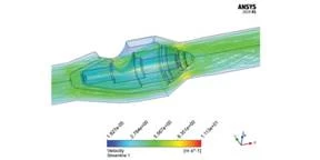
The body shape has been optimized
Low
operating time
The annular section around the disc requires a smaller stroke than other valve
types to generate a specific flow rate.
The disc is pressure balance;, in fact the line pressure acts on both sides of
disc when the valve is in the open position. This, in addition to the low mass
of internals, permits easy operation, fast stroking speeds and low operating
forces.
With the valve in the closed position the valve will continue to function
correctly even if there is a high pressure build-up on either the upstream or
the downstream side of the valve.
Long-life
& tight shut-off sealing capability
Seat sealing is designed to provide long life tight shut-off performance under
the most severe operating conditions. Seals are not exposed to flow stream when
valve is in open position, during the throttling phase the flow is choked by
metal parts preventing exposure of the seal to the high velocity flow. Only in
the last millimeters of the valve stroke will the seal be introduced into its
seating and energized.
The valves are supplied with primary metal, secondary soft sealing system that
allows a fully bidirectional tight shut-off.
Low
maintenance / High reliability
Proper design and manufacturing of the seat ring and the disc sealing surface
guarantee that valves provide tight shut-off performances combined with long
operational life.
Under normal operating conditions the valves do not require any special
maintenance and the over-sizing of critical components and gasket redundancies
increase the reliability of the valve.
FMECA study has been used to verify that the valve design was within the
customer design parameters.
Conclusions
The axial flow valve design is the preferred option in Onshore/Offshore HIPPS
applications when extremely quick closing is required. In fact, both the short
stroke and the absence of friction between seat and disc contribute to the
achievement of an extremely quick closing time.
Actuators for HIPPS application are designed for fast, reliable stroking during
the entire service life. These actuators will close the valve by means of the
mechanical energy of the spring.
Valves for HIPPS will remain in the open position for long periods of time that
shall not influence the closing time; the axial flow design reduces the
variations of required closing force. The pressure balanced disc minimizes the
break to close thrust while the force of the compressed spring is at its
maximum.