 +86 512 68781993


Gaskets Are Not Created Equal
GREG JOHNSON
http://www.valvemagazine.com/
2018-06-20 15:50:37
Gaskets are near the bottom of the food chain of valve components; trim, body materials and packing seem to get a lot more press. But gaskets serve an important purpose: They are the static seal between non-moving valve components—usually the body and bonnet. Without gaskets, those two (and sometimes three) body or body/bonnet parts would have great difficulty sealing after assembly. It’s important for maintenance and repair personnel to understand what gaskets are and how they work because so many of those gaskets will need to be replaced or repaired.
Gaskets have been around as long as valves have been manufactured. Although some gasketless designs such as threaded and welded bonnet types exist, the bulk of today’s linear and check valves all have gaskets.
The earliest gaskets were made from organic materials such as jute or flax. Natural rubber was a popular choice before the chrysotile-based asbestos materials came into vogue at the turn of the 20th century. Asbestos, rubber and soft iron (actually soft steel) were the industrial gasket materials of choice until about the 1950s.
While gaskets are found in nearly all two-piece-bodied valves, the bulk of the attention on gasket materials and gasket design is focused on the linear or multi-turn type of valves. In many cases, quarter-turn valve gaskets are more of an engineered seal or component part, rather than an off-the-shelf gasket. Quarter-turn gaskets or seals are also usually much smaller in cross-section than their multi-turn cousins.
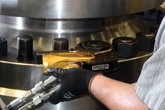
TODAY, MOST REASSEMBLY OF BODY/BONNET BOLTING
REQUIRES THE USE OF SPECIALIZED TORQUE-CONTROL EQUIPMENT,
SUCH AS THIS HYDRAULIC BOLT TIGHTENER
THREE STYLES
Today’s gasket styles can be differentiated by the type of force generated to cause them to seal. The simplest gaskets are called “crush” gaskets. These flat gaskets rely on brute force to tightly squeeze the gasket between two flat surfaces, filling any imperfections in the flange sealing surfaces. The most common crush-style materials are polytetrafluoroethylene (PTFE), rubber and soft corrugated metal. These materials work well for containing moderate pressures of 300 psi or less.
“Controlled-crush” gaskets use force to seal, although the crush rate is usually limited by tangs or geometric designs that prevent over-torqueing. The most common controlled crush gasket is the spiral-wound type. To achieve maximum effectiveness, the compression is limited to about 20-30% of relaxed gasket height. Additionally, the spiral-wound gasket must be contained on its inner diameter (ID) and outer diameter (OD) to prevent delamination of the alternating rings of metal and filler material.
“Controlled-crush” gaskets use force to seal, although the crush rate is usually limited by tangs or geometric designs that prevent over-torqueing. The most common controlled crush gasket is the spiral-wound type. To achieve maximum effectiveness, the compression is limited to about 20-30% of relaxed gasket height. Additionally, the spiral-wound gasket must be contained on its inner diameter (ID) and outer diameter (OD) to prevent delamination of the alternating rings of metal and filler material.
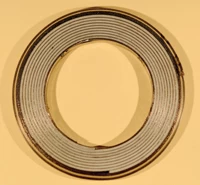
This image shows the laminations of alternating
stainless steel and PTFE on this 3-inch diameter spiral-wound gasket.
Spiral-wound gaskets can be made in virtually any size and diameter.
A newer style of controlled-crush gasket is the Kammprofile type. This gasket relies on a multitude of tiny serrations designed to deflect or bite into a surface material such as graphite. Kammprofile types have been successfully adapted to many applications that once were the sole domain of the spiral-wound gasket.
A third controlled-crush gasket is the ring-type-joint (RTJ). The RTJ gasket relies on an oval or octagonal ring resting between two, smoothly machined grooves. The RTJ ring must be softer than the mating grooves to allow for slight deformation or “fit” into the grooves. Like many other valve innovations, the RTJ design originated in Texas. It was first used in the West Texas oilfields in the 1920s and, until the greatest generation all retired, it was also known as a “Texas Joint.”
The last style of gasket is the “pressure assisted” design. These gaskets are also known as pressure seals. They originated in Germany in the 1920s, where they were used for high-pressure research work. It wasn’t until the mid-1940s that the pressure seal found use in valve design as an excellent high-temperature, high-pressure gasket seal.
Originally, pressure seal rings were made of soft steel and coated with silver. This design worked well, but the silver plating was easy to scratch. Developments in the late 20th century resulted in pressure-seal gaskets made of a composite of stainless steel and graphite. These composite gaskets offer superior sealing because of their ability to negate the negative effects of minute scratches or deformities in the valve body at the point where the pressure seal makes contact.
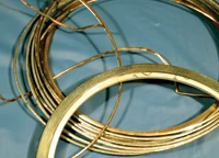
A delaminated spiral-wound gasket is shown next to the
pristine replacement gasket.
Delamination can cause catastrophic leaks and
damage downstream piping components.
GASKETS FOR SPECIFIC APPS
Valve types, pressure classes and sizes each use specific gasket types for several reasons. Valves in low-pressure, ambient applications such as water and wastewater work very well with sheet materials such as rubber or in cases where the media is harsh, PTFE. Rubber O-ring seals are also often used as gaskets in these types of valves.
Many valves in the chemical industry are small and commonly see only lower pressures. These valves, often made of stainless steel, also function very well with sheet PTFE materials. In cases where a bit more strength is required of the PTFE, additives of materials such as glass and graphite can be mixed with the base material before final forming. For round-bonnet Class 300 valves, either the spiral-wound or Kammprofile type is specified.
Most steel industrial valves in Class 150 use a wavy soft-carbon steel gasket sheathed in graphite. This combination of graphite and easily-deformed soft steel works well for the rectangle-shaped bonnets of the Class 150 gate valves. The round bonnets of Class 150 check and globe valves are usually home to either the spiral-wound or Kammprofile gasket. Gasket specifications for gate, globe and check valves in refinery and petrochemical service are detailed in American Petroleum Institute (API) specifications: 594, 600, 602, 603 and 623.
As pressures get higher, the design of appropriate gasket seals also changes. API refinery valves in Class 300 and in some cases Classes 600, 900 and 1500, use a fully contained spiral-wound or Kammprofile gasket type. When pressures are greater than Class 300, the RTJ or pressure seal design is often used. RTJ gaskets are available in soft carbon steel, low alloy steels and stainless steels to meet virtually any valve body material requirement.
The pressure seal gasket is at home in the highest pressure/temperature applications. Its ability to seal tighter as the pressure rises is an advantageous feature. However, pressure-seal gaskets also can be very fickle if their diet of high pressure is greatly reduced. This once-tight, high-pressure seal can easily leak if the working pressure is dropped significantly and the bonnet bolts are not retorqued.
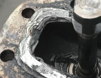
This is an example of a failure of a graphite-laminated
soft steel gasket on a Class 150 gate valve.
The failure created a catastrophic leak.
PROPER TORQUEING
For all these gaskets to operate as they are designed to, proper torque must be applied to the bolting, and hence to the gasket itself. The load applied to the gasket is a result of the spring force applied by the gasket bolting. The “spring” comes from tightening the bolting to a percentage of its maximum yield strength. As long as the torque is less than the maximum yield strength, the bolt will function as a tightly-wound spring. If the yield strength is exceeded, the bolt will deform and become slightly longer than it originally was—it will not return to its original length and it will become “loose.”
In years past, the primary bolt-tightening tool was a hand-held wrench or an air-powered impact wrench. With today’s emphasis on quality manufacturing and remanufacturing (repair), combined with concern over fugitive emissions, the brute-force torqueing methods of the past are no longer in vogue. In today’s valve assembly plants and repair shops, the annoyingly loud chatter of impact wrenches has been quietly replaced by the near-silence of hydraulic-controlled torque wrenches. These devices provide the exact amount of torque where and when needed for tightening gasket bolting.
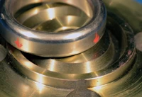
RTJ gaskets require carefully machined smooth grooves
in order for the metal gasket to seal properly.
The RTJ gasket must also be softer than the groove material so
it can slightly deform into the groove area.
WHAT CAN GO WRONG?
As long as the torque is correct, the flange surfaces are exactly parallel, the material of the gasket is right, the dimensions of the gasket are the right ones, the surface finish of the flange faces is right and the joint was assembled correctly—nothing can go wrong. All valve bonnet gaskets work perfectly and never leak!
The reality is that sometimes gasketed valve joints do fail whether they’re flat gaskets or RTJ gaskets. The most common cause is incorrect load on the gasket. This can come from using the wrong gasket or not tightening the bolting as required to effect a good seal. The incorrect tightening problem can result from either under- or over-torqueing the bolting.
Spiral-wound gaskets can fail catastrophically if a shoulder or ring on the ID is not there to prevent delamination of the metal and filler material rings. The use of a crush-style gasket in an application that calls for a controlled-crush style can also cause a major leak. The finish of gasket surfaces must meet the requirements of the gasket type. Any lateral scratches across the gasket sealing surface can cause a leak path. If an RTJ gasket ring is too hard and the bolting torque too high, the ring gasket can deform the body and bonnet flange grooves, resulting in a leaky joint.
Gasket designs and assembly techniques have improved alongside advances in the design of the valves where they are installed. Although there is no one perfect gasket, the multitude of designs and materials available today make selecting the right gasket for each application much easier than it was 75 years ago. However, proper assembly techniques are required to ensure that these gaskets work as they should.
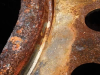
RTJ grooves must be smooth on the sides where the
gasket touches or leakage will occur. This damaged
RTJ groove will require machining and possibly weld repair.