+86 512 68781993


Analysis of the performance of control valve PTFE packing
Various properties of filler materials result in different performance characteristics. This article examines the properties and benefits of various valve packings, with a particular focus on friction characteristics and their effect on control valve performance.
Importance of packing friction
Some industries, such as nuclear power, often use sophisticated diagnostic tools that allow end users to simulate operating conditions by cycling valves on and off during maintenance activities. These tools track many variables in valve and actuator assemblies during travel. If a control valve fails a diagnostic test or has an abnormal result, one of the first variables analyzed is the friction curve created by the resistance to stem movement created by the stem sliding through the valve plug.
The main benefit of these diagnostic tools is the ability to generate friction curves. Typically, these tools draw a graph showing the amount of friction created in the valve system over the entire valve travel. The diagnostic software will then independently calculate the friction during the opening and closing strokes, as well as the average friction for the combined fully open and fully closed strokes. This friction curve can be used to identify several potential problems that may exist inside the valve before it is put back into service.
When looking at the friction curve, it's easier to identify problems, such as if the valve has too much or too little friction, or if the valve has non-linear friction, which could indicate valve stem wear or necking. Although too little friction may be created in some cases, this article focuses on reducing packing friction to increase valve margin and operability. Increased friction can be achieved relatively simply by increasing the seal ring or packing stress. Reducing friction while maintaining leak-free service is much more complicated.
The challenge of reducing friction
Valves with excessive packing friction can suffer from many negative effects, including wobble or overcorrection of the actuator. rod wear; actuator degradation; and reduced equipment reliability and service life. All of these factors can lead to downtime or equipment failure. Reducing packing friction while maintaining leak-free operation requires a delicate balance that is largely dependent on the packing of the valve.
The friction generated by valve packing is usually expressed as the product of two variables f and y in the packing friction equation:
Packing Friction (L) = Gs π f * y * Di * H * N, where Gs is the gland stress, π is 3.14159, fy is the packing friction coefficient, Di is the inner diameter (stem diameter) of the valve packing, and H is Height of packing rings, N is the number of packing rings.
The dimensionless fy value is the product of two separate values, the coefficient of friction of the filler material (denoted by "f") and the transfer ratio of axial stress to average radial stress (denoted by "y"). These two values are multiplied together to form a single variable, fy, which represents the total friction coefficient of the packing on the valve stem.
Manufacturers of valve packing have spent years reducing the fy value of their packing products in an effort to identify the ideal material combination to provide the end user with packing that provides consistent sealing performance while maintaining low friction. Many packaging types excel in one of these areas and lack the other. In other words, where one material may seal effectively but generate high friction loads, another material may generate low friction loads but struggle to maintain sealing performance over multiple cycles.
This imbalance often forces the end user to select filler types based on the strength of one capability, while compromising its performance on the other.
Valve packing material
For many years, most valve packings were made of asbestos and loaded with various forms of artificial lubricants. Eventually, the negative effects of inhaling asbestos were realized, so the industry looked for and found a relatively inexpensive and abundant alternative: graphite. Graphite is readily available and has been used as a lubricant for decades.
For most valves, such as pressure seal gate valve this widely accepted alternative is a combination of braided graphite yarn and molded flexible graphite. Braided yarn rings are used with die-formed flexible graphite packing rings for stem sealing. This configuration typically includes three die-formed flexible graphite rings in the middle and two braided yarn rings at the ends to prevent extrusion of the inner die-formed rings.
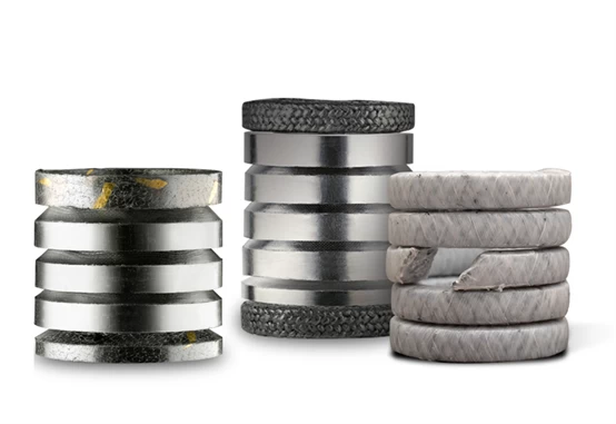
Although this solution is inexpensive and provides an effective seal, diagnostic testing has shown that the seal kit produces high friction and has a relatively limited life in the control valve. One of the features of using compression molded flexible graphite rings is that when these rings are made, they are typically preformed to a density of 90 pounds per cubic foot. To achieve this density, the graphite must be compressed in a mold to an axial stress of approximately 2,000-2,200 psi. This means that the moulded ring needs to overcome the moulding pressure in order to seal. Therefore, the typical recommended gland stress range for mold forming fillers is 3,000-5,000 psi. When considering the aforementioned packing friction equation, it is clear that as greater gland stress is applied, greater packing friction is applied to the rod.
Properties and Benefits of PTFE Packing
The introduction of packing containing polytetrafluoroethylene (PTFE) was a revolution in the field of control valve packing. The many mechanical properties of PTFE are attractive and they can be used as stem sealants for control valves. It is non-porous, chemically inert, and remains stable at relatively high temperatures (typically has an upper temperature limit of 350°F or 177°C to 615°F or 324°C, depending on the PTFE of the filler properties of ethylene). Over the past few decades, PTFE-containing valve packing has been used to reduce friction between the valve stem and packing, allowing the valve to operate more smoothly while reducing wear and improving equipment reliability.
PTFE-based packing is not without limitations, and not all operating conditions are applicable to this material. Temperature and radiation limits must be considered.
To verify and quantify the benefits of PTFE-based packing using available information, the authors of this paper and their research cite a comparison of coefficients of friction in control valves using various forms of valve packing. The study is not intended to be considered scientific - proper statistical analysis has not been performed. But this article will compare the information to examine the differences in filler types. The data used in this study was obtained from a web-based valve filler database software used in the home power industry.
Compare research
The packing database used in the study allows the end user to enter certain valve parameters to predict friction caused by packing sets. The user enters various data such as the diameter of the valve stem and stuffing box, the diameter of the packing gland studs, the number of packing gland studs, and the required packing (gland) stress. The software then uses a set of stored default fy values to predict the total friction caused by valve packing. These predicted friction values are especially important for valves that are required to operate within a certain time domain. If the expected friction is too high, the end user can choose to use alternative packaging materials or reduce the number of rings to bring the expected friction back into an acceptable range.
The default fy values associated with each filler type are based on input from the packaging manufacturer, usually from internal testing. Typically, this test is performed under laboratory conditions and may represent an "ideal" situation, while the actual coefficient of friction may vary widely depending on a number of factors in the field. To more accurately predict fy values, a feature has been added to the software application to allow the end user to input the actual measured friction force obtained from the diagnostic tests of each control valve. Based on the actual data at the site, the program will back-calculate the actual measured fy value of the valve packing for each individual valve.
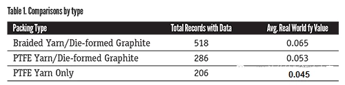
The goal is to collect enough data points so that the defaults can be modified based on field data to more accurately predict actual friction. This data provides the ability to compare aggregated data. When plotted into a spreadsheet, the data shows how certain package types compare to each other relative to their actual fy values. One of the most meaningful comparisons is the actual fy value of the standard yarn and graphite filler group versus the PTFE-based filler group.
Compare real values
Approximately 1,000 records were compared and the average actual fy value was calculated for each package type. As shown in Table 1, the average actual fy value of the packing containing braided yarn ring and molded flexible graphite without PTFE was 0.065; the average actual fy value of the PTFE braided ring with the molded flexible sealing ring was 0.053 ; those packings containing PTFE braided rings without die-formed flexible graphite rings had an actual fy value of 0.043.
Although the data set is relatively small due to the large number of valves that have been diagnostically tested since the data tracking began, the results demonstrate the consistent ability of PTFE-based valve packing to reduce friction. The data shows that the use of a PTFE-based backing can reduce the coefficient of friction by about 34%, which means a significant increase in actuator margin and valve operability.
Based on this
available data, PTFE valve packing outperforms graphite and yarn packing in
control valve applications.