Pneumatic control valve
Pneumatic control valve
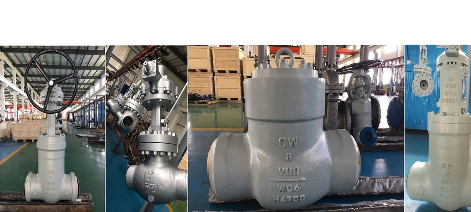
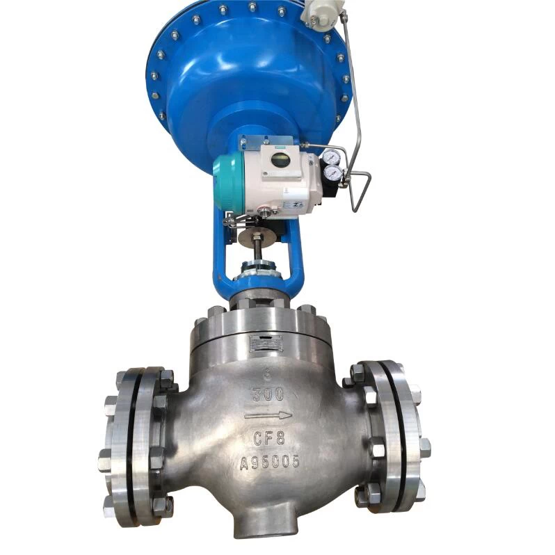
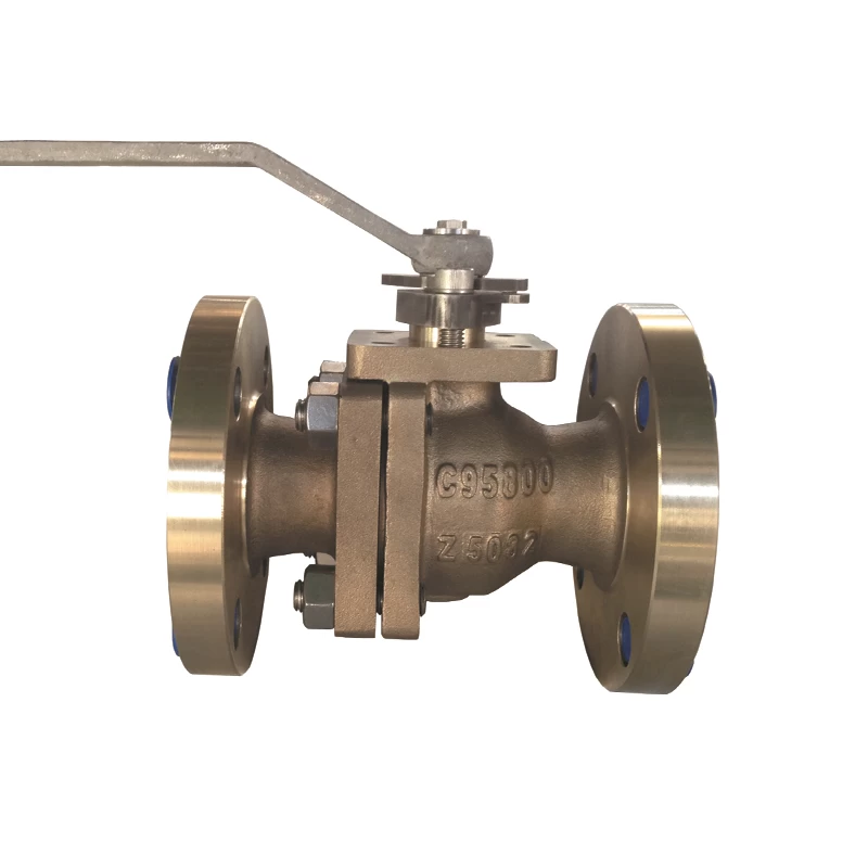
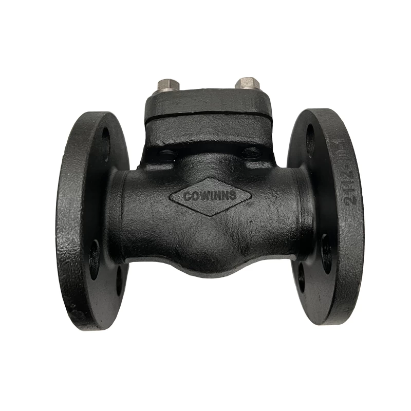
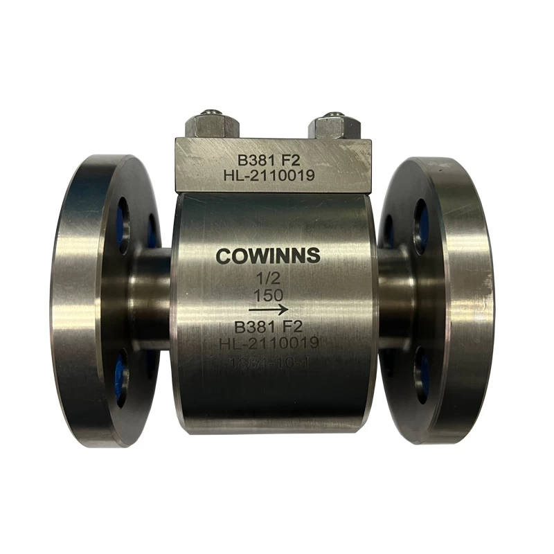
The pneumatic control valve is one of the widely used industrial process control devices in the power industry. The high pressure control valve is essential in regulation systems and is an important component in the formation of industrial automation systems.
Working principle:
The pneumatic control valve uses compressed air as the power source, with a cylinder as the actuator, and relies on accessories such as electrical valve positioners, converters, solenoid valves, and pressure-holding valves to drive the valve. It achieves on/off or proportional regulation by receiving control signals from the industrial automation control system to regulate various process parameters of the pipeline medium, such as flow, pressure, temperature, etc. The characteristics of the pneumatic control valve are simple control, quick response, and inherent safety, without the need for additional explosion-proof measures.
Working principle of pneumatic control valve (diagram)
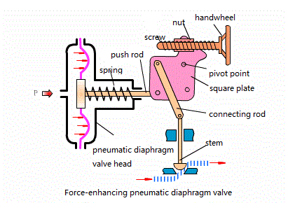
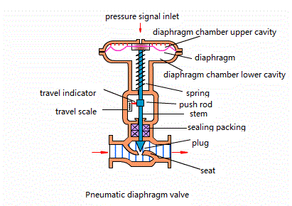
The pneumatic control valve is typically composed of a pneumatic actuator and a control valve, which are connected, installed, and debugged together. The pneumatic actuator can be classified into two types: single-acting and double-acting. The single-acting actuator has a return spring, while the double-acting actuator does not. In the case of a single-acting actuator, it can automatically return to the valve's initial open or closed position when the power supply is lost or a sudden failure occurs.
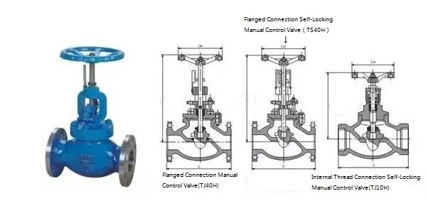
The pneumatic control valve is classified into two types based on the action mode: air-to-open and air-to-close, also known as normally open and normally closed. The air-to-open or air-to-close function of the pneumatic control valve is typically achieved through the different assembly methods of the actuator's forward and reverse actions and the valve's structural design.
Mode of operation of the pneumatic control valve
The air-to-open (normally closed) type operates by increasing the air pressure on the diaphragm, causing the valve to move in the direction of increased opening. When the input air pressure reaches its maximum limit, the valve is fully open. Conversely, when the air pressure decreases, the valve moves toward the closing direction, and when there is no input air, the valve is fully closed. Therefore, we commonly refer to the air-to-open type control valve as a fail-closed valve.
The air-to-close (normally open) type operates in the opposite direction to the air-to-open type. When the air pressure increases, the valve moves in the direction of closing. When the air pressure decreases or there is no air, the valve moves toward opening, or fully opens. Therefore, we commonly refer to the air-to-close type control valve as a fail-open valve.
The selection of air-to-open or air-to-close is based on the safety perspective of the process production. It depends on whether the control valve should be in the closed position or the open position for safety when the air supply is cut off.
For example, in the combustion control of a heating furnace, the control valve is installed on the fuel gas pipeline and regulates the fuel supply based on the temperature in the furnace or the temperature of the heated material at the furnace outlet. In this case, it is safer to choose an air-to-open valve, because if the air supply is interrupted, it is more appropriate for the valve to be closed rather than fully open. If the fuel valve is fully open when the air supply is cut off, it could lead to excessive heating, which is dangerous. Similarly, for a heat exchanger cooled by cooling water, where hot material exchanges heat with cooling water inside the exchanger, the control valve is installed on the cooling water pipeline and regulates the cooling water flow based on the temperature of the material after heat exchange. In the event of an air supply interruption, it is safer for the control valve to be in the open position, so an air-to-close (FO) control valve is preferred.
Valve Positioner
The valve positioner is a major accessory of the control valve and is widely used in conjunction with pneumatic control valves. It receives the output signal from the controller and uses its own output signal to control the pneumatic control valve. After the control valve operates, the displacement of the valve stem is fed back to the valve positioner through a mechanical device, and the valve position status is transmitted to the higher-level system via an electrical signal. Valve positioners can be classified into pneumatic valve positioners, electro-pneumatic valve positioners, and smart valve positioners based on their structure and working principle.
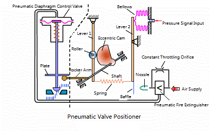
The valve positioner can increase the output power of the control valve, reduce the transmission delay of the control signal, accelerate the movement speed of the valve stem, improve the valve's linearity, overcome the frictional force of the valve stem, and eliminate the effects of unbalanced forces, thereby ensuring the correct positioning of the control valve.
Actuators are classified into pneumatic actuators and electric actuators, with linear and rotary types. They are used to automatically or manually open and close various types of valves, dampers, and other equipment.
Pneumatic control valve installation principles
(1) The pneumatic control valve should be installed at a certain height from the ground, with adequate space above and below the valve to facilitate disassembly and maintenance. For control valves equipped with pneumatic valve positioners and handwheels, it is essential to ensure that operation, observation, and adjustment are convenient.
(2) The control valve should be installed on a horizontal pipeline and should be vertical with respect to the pipeline both above and below. Generally, support should be added below the valve to ensure stability and reliability. In special cases where the valve needs to be installed horizontally on a vertical pipeline, the valve should also be supported (except for small-diameter control valves). During installation, care should be taken to avoid adding additional stress to the valve.
(3) The operating environment temperature of the control valve should be between -30°C and +60°C, with a relative humidity not exceeding 95%.
(4) There should be a straight pipe section before and after the control valve, with a length no less than 10 times the pipe diameter (10D), to avoid short straight sections that may affect the flow characteristics of the valve.
(5) If the valve size differs from the pipeline size, a reducing pipe should be used for connection. For small-diameter control valves, threaded connections may be used. The flow direction arrow on the valve body should be consistent with the flow direction of the fluid.
(6) A bypass pipe should be installed to facilitate switching or manual operation, allowing for maintenance of the control valve without shutting down the system.
(7) Before installation, the control valve must be thoroughly cleaned to remove any foreign objects in the pipeline, such as dirt, welding slag, etc.
Common Faults and Troubleshooting
1.Control Valve Fails to Actuate
- First, verify whether the air supply pressure is normal and check for any faults in the air source. If the air supply pressure is normal, check if the positioner or electro-pneumatic converter's amplifier is outputting. If there is no output, the amplifier's constant throttling hole may be blocked, or moisture in the compressed air may have accumulated at the amplifier’s ball valve. Use a fine steel wire to clear the throttling hole and remove any debris or clean the air source.
- If everything appears normal, and there is a signal but no action, the fault may lie with the actuator (such as a malfunction), the valve stem being bent, or the valve plug being stuck. In this case, the valve must be disassembled for further inspection.
2. Control Valve Sticking or Jamming
- If the valve stem's reciprocating movement is sluggish, the valve body may contain viscous substances, carbon deposits, excessive packing pressure, or the aging of PTFE (polytetrafluoroethylene) packing, or the valve stem may be bent or scratched. The issue of control valve jamming commonly occurs in systems that have just been put into operation or shortly after major repairs. It is often due to welding slag, rust, or other debris in the pipeline clogging the throttle or guiding parts, causing poor medium flow. It may also happen during maintenance when the packing is too tight, increasing friction and leading to situations where small signals fail to actuate or large signals cause excessive movement.
To address this issue, try quickly opening and closing the bypass line or control valve to let debris be flushed out by the medium. Alternatively, use a pipe wrench to clamp the valve stem and, under added signal pressure, apply force in both directions to rotate the stem and allow the valve plug to move past the obstruction. If this does not resolve the issue, increase the air supply pressure or driving power and move the valve stem up and down several times to clear the blockage. If the problem persists, disassemble the valve. However, this requires strong professional skills and should only be performed with assistance from qualified personnel to avoid more serious consequences.
3. Valve Leakage
Control valve leakage generally includes internal leakage, packing leakage, and leakage caused by deformation of the valve plug and seat. Below are the analyses of these common issues.
(1) Internal Leakage
- Cause: The valve stem may be of incorrect length. In the case of an air-to-open valve, if the valve stem is too long, the distance from the stem's upper (or lower) part may be insufficient, resulting in a gap between the valve plug and seat. This gap prevents proper contact and leads to internal leakage. Similarly, for air-to-close valves, if the stem is too short, there may also be a gap preventing full contact between the plug and seat, resulting in inadequate sealing and internal leakage.
- Solution: The length of the valve stem should be adjusted by shortening or extending it to ensure the control valve is properly sealed and no internal leakage occurs.
(2) Packing Leakage
- Cause: After the packing is loaded into the packing box, an axial pressure is applied to it by the gland. Due to the plastic deformation of the packing, it generates radial force, making it tightly contact the valve stem. However, this contact is not uniform—some areas may be loose, while others are tight, and in some areas, there may be no contact at all. During use, there is relative motion between the valve stem and the packing, known as axial movement. Over time, especially under high temperature, high pressure, and permeable fluid media conditions, packing leakage is a common issue. The primary cause of packing leakage is interface leakage, and for textile packing, leakage may occur as fluid seeps through small gaps between packing fibers.
Solution: To facilitate the packing installation, a chamfer should be applied to the top of the packing box, and a metal protective ring with small gaps and corrosion resistance should be placed at the bottom. This protective ring should not be inclined to prevent packing from being pushed out by the pressure of the medium. The surface in contact with the packing in the packing box should be finely machined to improve surface smoothness and reduce packing wear. Flexible graphite packing is recommended due to its excellent gas tightness, low friction, minimal wear, easy maintenance, and good pressure and heat resistance. It is also resistant to internal medium corrosion and does not cause pitting or corrosion of metals that come into contact with the valve stem or packing box. This ensures the reliability of the packing seal and extends its service life.
(3) Leakage Due to Deformation of Valve Plug and Seat
Cause: Leakage in the valve plug and seat is mainly due to casting or forging defects during the manufacturing process of the control valve, which can lead to increased corrosion. The corrosive medium passing through and the scouring action of the fluid medium can also contribute to the leakage. Corrosion mainly manifests in the form of erosion or cavitation. When a corrosive medium flows through the control valve, it erodes and impacts the materials of the valve plug and seat, causing them to become elliptical or take other deformed shapes. Over time, this deformation leads to improper sealing, resulting in leakage.
- Solution: Pay attention to the selection of materials for the valve plug and seat. Corrosion-resistant
materials should be chosen, and products with defects such as pitting or sand holes should be eliminated. If the deformation of the valve plug and seat is not severe, fine sandpaper can be used to polish the affected areas, eliminating traces and improving the sealing surface's smoothness to enhance sealing performance. If the damage is severe, the valve plug and seat should be replaced with new parts.
4. Oscillation
Oscillation in the control valve can occur when the spring stiffness is insufficient, causing unstable and sharp fluctuations in the valve's output signal. It can also happen if the selected valve's frequency matches the system frequency, or if there is severe vibration in the pipeline or the base, causing the valve to vibrate as well. Improper selection can also lead to oscillation when the valve operates at small openings, where drastic changes in flow resistance, flow rate, and pressure occur. When these changes exceed the valve's stiffness, its stability decreases, potentially causing oscillation.
Since the causes of oscillation are multifaceted, each issue should be analyzed specifically. For minor oscillations, increasing the stiffness can eliminate the problem, such as by selecting a valve with a higher-stiffness spring or switching to a piston actuator structure. If there is severe vibration in the pipeline or the base, the vibration interference can be reduced by adding additional supports. If the valve's frequency matches the system's frequency, it is necessary to replace the valve with one of a different structural design. Oscillation caused by operation at small valve openings typically results from improper valve selection, specifically due to the valve’s large flow coefficient (C-value). In this case, the valve should be re-selected with a smaller C-value, or a split-range control system or pilot-operated valve (sub-valve) should be used to mitigate oscillation at small openings.
5. Excessive Noise from Control Valves
When fluid flows through a control valve, if there is a large pressure differential between the inlet and outlet, cavitation can occur at components such as the valve plug and seat, causing noise. If the selected valve's flow coefficient is too large, the valve may operate at small openings, generating noise. In such cases, the valve's flow coefficient should be appropriately reselected to mitigate noise caused by small valve openings. Below are several methods to reduce or eliminate noise:
(1) Resonance Noise Elimination
Resonance occurs only when the control valve vibrates, amplifying energy and producing loud noise (over 100 decibels). Some valves may vibrate intensely with relatively little noise, while others may have weak vibrations but very high noise. In some cases, both the vibration and the noise are intense. This noise produces a single-tone sound, typically in the frequency range of 3000 to 7000 Hz. Clearly, eliminating resonance will naturally cause the noise to disappear.
(2) Cavitation Noise Elimination
Cavitation is a major source of fluid dynamic noise. When cavitation occurs, the collapse of vapor bubbles produces high-speed impacts that cause intense localized turbulence, resulting in cavitation noise. This noise has a wide frequency range and resembles a "gravel-like" sound, similar to the noise produced by particles like sand in the fluid. Reducing or eliminating cavitation is an effective way to reduce noise.
(3) Use of Thick-Walled Pipelines
Using thick-walled pipes is one method to treat noise. Thin-walled pipes can increase noise by 5 decibels, while thick-walled pipes can reduce noise by 0 to 20 decibels. For example, with a DN200 pipe, using different wall thicknesses (6.25, 6.75, 8, 10, 12.5, 15, 18, 20, 21.5mm) can reduce noise by -3.5, -2 (increase), 0, 3, 6, 8, 11, 13, and 14.5 decibels, respectively. However, the thicker the wall, the higher the cost.
(4) Use of Sound-Absorbing Materials
This is a common and highly effective method for treating noise. Sound-absorbing materials can be wrapped around the noise source and the pipeline downstream of the valve. It should be noted that noise propagates long distances through the fluid, so the effectiveness of sound absorption stops where the material or thick-walled pipe ends. This method is suitable for situations where the noise level is not too high, and the pipeline is relatively short, but it can be costly.
(5) Use of Inline Silencers
This method is suitable for reducing air-driven noise. It can effectively eliminate noise within the fluid and suppress noise transmitted to the solid boundaries of the system. This method is most effective and economical in places with high mass flow rates or large pressure drops across the valve. Using an absorption-type inline silencer can significantly reduce noise. However, from an economic standpoint, the noise level is generally reduced by about 25 decibels.
(6) Use of Soundproof Enclosures
Soundproof enclosures, rooms, or buildings can isolate the noise source, reducing the noise level in the external environment to an acceptable level for people.
(7) Series Throttling Method
In cases where the pressure ratio across the control valve is high (△P/P1 ≥ 0.8), the series throttling method is used. This involves distributing the total pressure drop between the control valve and fixed throttling components downstream of the valve, such as diffusers or porous flow limiters. This is one of the most effective methods to reduce noise. To achieve the best diffuser efficiency, the diffuser design (including its shape and size) must be tailored to the specific installation, ensuring that the noise level produced by the valve matches the noise level generated by the diffuser.
(8) Selection of Low-Noise Valves
Low-noise valves feature tortuous flow paths (multiple porous channels or grooves) through the valve plug and seat to gradually slow down the fluid flow, thus preventing the generation of supersonic flow at any point in the path. There are various forms and structures of low-noise valves available (some designed for specific systems). When the noise level is not excessively high, a low-noise sleeve valve can reduce the noise by 10–20 decibels, which is the most economical low-noise valve option.
Valve Positioner Faults
Conventional positioners operate based on a mechanical force-balance principle, using a nozzle-flapper technique. They have the following common faults:
①. Mechanical Force-Balance Issues: The positioner has many moving parts, making it susceptible to temperature and vibration effects, which can cause fluctuations in the control valve.
②. Clogging Due to Dust: The nozzle, which has a small aperture, can easily become blocked by dust or unclean air sources, preventing the positioner from functioning properly.
③. Changes in Spring Elasticity: The elasticity of the spring in force-balance positioners can change in harsh environments, leading to non-linear behavior of the control valve and reduced control quality.
④.Intelligent positioners, which consist of components such as a microprocessor (CPU), A/D and D/A converters, operate based on electric signals rather than the mechanical force balance. This allows them to overcome the limitations of conventional positioners. However, in emergency shutdown situations (such as for emergency shut-off valves or emergency vent valves), these valves must remain stationary at a certain position and only move reliably during an emergency. If they stay at a certain position for an extended period, the electrical converter may lose control, leading to the risk of no movement with small signals. Furthermore, the position sensors (potentiometers) used in valves may experience resistance changes in the field, resulting in the risk of no movement with small signals or the valve opening fully with large signals. To ensure the reliability and usability of intelligent positioners, frequent testing is required.
 +86 512 68781993
