+86 512 68781993


The impact of pipeline resistance on head and the calculation of pipeline losses
The impact of pipeline resistance on head and the calculation of pipeline losses
As we know, a pipeline is a solid material, while water is a substance that flows easily. If the water inside the pipeline is flowing, a portion of its energy must be converted into heat and 'lost,' which means that some of the water pressure (or head) is lost. This is a reflection of objective reality and an inevitable law of fluid motion. Generally, we refer to this phenomenon of energy conversion as energy loss (or hydraulic loss, or loss of head), which is calculated in meters.
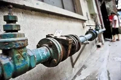
How much does pipeline resistance affect the head? Some users, after measurement, find that although the vertical distance from the reservoir or water tower to the water source is slightly less than the pump head, the water flow is still low or the water cannot be lifted. The reason is often that the pipeline is too long and has too many bends, causing excessive resistance loss in the pipeline. Generally, a 90-degree bend causes more resistance than a 120-degree bend. Each 90-degree bend results in a head loss of about 0.5 to 1 meter, and every 20 meters of pipeline resistance can cause a head loss of about 1 meter. In addition, some users also arbitrarily change the pipe diameter of the pump's inlet and outlet, which can also affect the head.
Are you clear about the reasons for hydraulic losses caused by water flow in pipelines?
1. The resistance caused by the roughness of the pipe wall.
2. The relative motion between the different layers of the water flow.
3. The vortices formed by sudden changes in the water flow inside the fittings.
The hydraulic losses in the pipeline (network) consist of both friction losses along the pipeline and local losses. In engineering practice, we must calculate and understand the amount of these losses in order to correctly select the pump and determine the required pump head.
The pipeline friction loss occurs due to the frictional resistance of water flow throughout the entire pipeline, and it is related to factors such as pipe wall roughness, pipe length, pipe diameter, and flow velocity. Based on hydraulic principles, a relationship can be established for it.
The friction loss along the pipe is directly proportional to the friction factor, which is influenced by the roughness of the pipe wall. Different materials have different roughness levels; for example, cast iron pipes are rougher, resulting in a higher friction factor, while plastic pipes are smoother, leading to a lower friction factor. The loss is also directly proportional to the length of the pipe, and inversely proportional to the pipe diameter. This means that, for a given flow rate, a smaller pipe diameter and higher flow velocity result in greater friction loss. Additionally, the loss is proportional to the square of the flow velocity. Of course, the calculation can be complex, but simpler methods can be used for estimation.
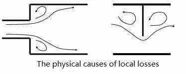
Local losses in the pipeline occur when the water flows through components such as bottom valves, valves, elbows, and reducers. These components cause changes in the flow pattern, altering both the direction and magnitude of the flow velocity, and generating vortices that cause turbulence and collisions between water flow. The hydraulic loss caused by these local resistances is referred to as local loss.
The magnitude of local losses is proportional to the square of the flow velocity through the pipeline components. It is also related to the shape and number of the components. The greater the variation in the cross-sectional shape of the components and the greater their number, the higher the local loss. Once the pipeline layout is determined, the pipeline loss head is generally calculated to determine the required design head for the pumping station, which is necessary for selecting the appropriate pump. However, the calculation process can be complex. To simplify, the calculation data can be compiled into tables for easy reference. Additionally, a rough estimation can be made: the loss head is approximately 30% to 50% of the actual lift height (measured from the terrain). For smaller pipe diameters and shorter pipelines, the higher value should be taken; for larger pipe diameters and longer pipelines, the lower value should be used.
The pressure loss of a liquid flowing through a straight pipe is caused by the friction of the liquid flow, known as the frictional pressure loss. It primarily depends on factors such as the length and inner diameter of the pipe, the flow velocity of the liquid, and its viscosity. The frictional pressure loss varies with the flow regime of the liquid. Laminar flow in a circular pipe is the most common flow regime in hydraulic transmission. Therefore, when designing hydraulic systems, it is often desired that the flow in the pipeline remains in a laminar state.
1. Laminar Flow
a). Pressure Loss in Laminar Flow
In hydraulic transmission, the flow of liquid is mostly in a laminar flow state. Under this condition, the pressure loss of the liquid flowing through a straight pipe can be calculated theoretically.
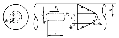
(1). The velocity distribution pattern of the liquid across the flow cross-section.
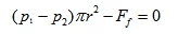
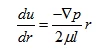
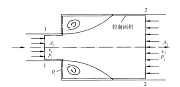
As shown in the figure above, the liquid undergoes laminar flow in a circular pipe with diameter d, placed horizontally. Consider a small cylindrical segment of the pipe, aligned with the pipe's axis, with radius r and length l. The forces acting along the axis of this small cylindrical segment include the pressure at the left end p1, the pressure at the right end p2, and the frictional force Ff on the cylindrical surface. The force balance equation for this segment is:
It can be seen from equation (2-6) that:
图片8
In the equation, μ is the dynamic viscosity.
Since the velocity increment du and the radius increment dr have opposite signs, a negative sign is added in the equation.
Additionally, Δp = p1 - p2.
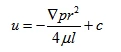
Substituting Δp and equation (2-45) into equation (2-44), we get:
Integrating the equation gives:
When r = R, u = 0. Substituting this into equation (2-47) gives:
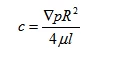
Then
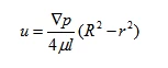
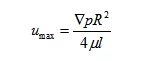
From the equation, it can be seen that the flow velocity u inside the pipe follows a parabolic distribution along the radial direction, with the maximum velocity occurring at the centerline, and its value is:
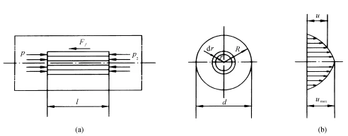
(2). Flow rate in the pipeline.
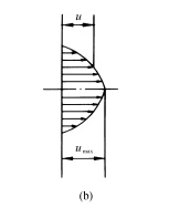
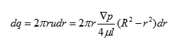
The volume of the paraboloid shown in Figure (b) represents the volume of liquid flowing through the flow cross-section per unit time, i.e., the flow rate. To calculate its volume, a thin circular ring with radius r and thickness d r is considered. The flow rate through this ring-shaped area is:
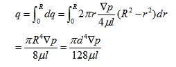
Integrating the equation gives the flow rate q:
(3) Average Flow Velocity. Let the average flow velocity inside the pipe be υ.
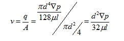
By comparison, the relationship between the average flow velocity and the maximum flow velocity can be obtained:

(4) Frictional Pressure Loss. In the laminar flow state, the frictional pressure loss of the liquid flowing through a straight pipe can be obtained from the following equation:
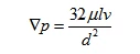
From the equation, it can be seen that in the laminar flow state, the pressure loss of the liquid flowing through a straight pipe is directly proportional to the dynamic viscosity, pipe length, and flow velocity, and inversely proportional to the square of the pipe diameter.
In practical calculations of pressure loss, to simplify the calculation, we use the relation μ = υdρ/Re, and substitute μ = υdρ/Re into the equation. Then, multiplying both the numerator and denominator by 2g, we get:
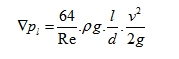
In the equation, λ is the friction factor. Its theoretical value is λ = 64/Re. However, in practice, due to various factors, for smooth metal pipes, λ = 75/Re, and for rubber pipes, λ = 80/Re.Pressure Loss in Turbulent Flow In laminar flow, the particles move in a regular axial direction with no transverse motion. One of the key characteristics of turbulent flow is that the liquid particles no longer move in a regular axial manner; instead, they mix and fluctuate during motion. This highly irregular motion leads to collisions between particles and the formation of vortices, which results in much greater energy loss in turbulent flow compared to laminar flow.
Due to the complexity of turbulent flow phenomena, a comprehensive theoretical study has not yet yielded satisfactory results. Therefore, experimental methods are still primarily used for research, with theoretical explanations provided alongside. As a result, the pressure loss of liquid flow in turbulent flow is still calculated using the following equation, where the value of λ depends not only on the Reynolds number Re, but also on the roughness of the pipe wall.
2. Local Losses
b). Local Pressure Loss
Local pressure loss is the pressure loss caused by the liquid flowing through components such as valves(some datas can be refer to LF2 check valve factory), elbows, and changes in flow cross-sectional area. When the liquid passes through these areas, both the direction and velocity of the flow change, causing the formation of vortices. This results in the collision of fluid particles, leading to significant energy loss.
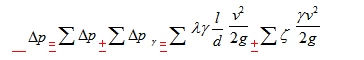
The local pressure loss at a sudden expansion can be expressed by the following equation:
In the equation, ξ is the local resistance coefficient, which can be theoretically derived only when the fluid flows through a suddenly expanded cross-section. In other cases, it must be determined experimentally. v represents the average flow velocity of the fluid, which generally refers to the velocity downstream of the local resistance. The total pressure loss in the pipeline system is the sum of all frictional (or length-based) pressure losses and all local pressure losses, i.e.,