 +86 512 68781993


What is a Valve Labyrinth Seal
What is a Valve Labyrinth Seal?
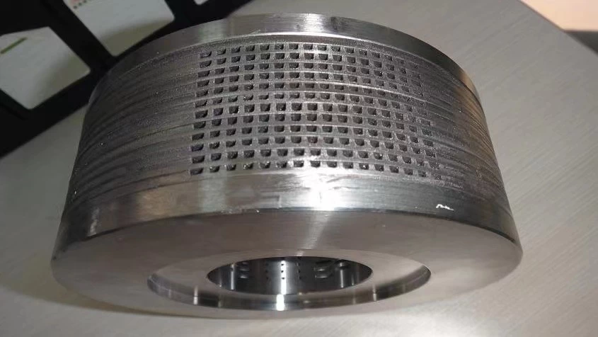
A labyrinth seal consists of a series of annular sealing teeth arranged sequentially around a rotating shaft. The gaps and expansion chambers formed between these teeth create a throttling effect on the sealed medium as it passes through the convoluted labyrinth, thereby achieving leakage prevention.
Due to the gap between the rotor and the casing in a labyrinth seal, there is no solid contact, no need for lubrication, and it allows for thermal expansion. This makes it suitable for high-temperature, high-pressure, and high-speed applications. Consequently, this sealing method is widely used for shaft end seals and interstage seals in turbines, gas turbines, compressors, blowers, and other dynamic seals.
Sealing Mechanism of Labyrinth Seals
The resistance created by fluid passing through the labyrinth, which reduces its flow rate, is known as the "labyrinth effect." For liquids, there are fluid dynamic effects, including hydraulic resistance and flow contraction effects. For gases, there are thermodynamic effects, such as heat conversion due to compression or expansion within the labyrinth. Additionally, there is the "permeation effect." The labyrinth effect is a combined result of these factors, making the sealing mechanism of labyrinth seals quite complex.
1. Friction Effect: When leaking liquid flows through the labyrinth, the friction due to liquid viscosity slows down the flow and reduces the leakage amount. Simply put, the friction effect consists of both longitudinal friction along the flow path and local resistance caused by the bends and geometric shapes of the labyrinth. Generally, longer flow paths, sharper turns, and pointed teeth result in greater resistance and significant pressure loss, reducing leakage.
2. Flow Contraction Effect: As fluid passes through the labyrinth gap, it contracts due to inertia, reducing the flow cross-section. If the orifice area is A, the minimum area of the contracted flow is Cc A, where Cc is the contraction coefficient. Additionally, the gas velocity changes after passing through the orifice. Assuming the ideal flow velocity is u1, the actual velocity is smaller, given by Cd as the velocity coefficient. Thus, the actual flow velocity u1 = Cdu1, and the flow rate through the orifice is q = CcCdAu1, where Cc·Cd = a (flow coefficient). The flow coefficient of a labyrinth gap depends on the shape of the gap, tooth profile, and wall roughness. For incompressible fluids, it also depends on the Reynolds number, while for compressible fluids, it depends on the pressure ratio and Mach number. The flow state before the gap also affects it. Therefore, in complex labyrinths, one cannot assume the flow coefficient of a single gap applies to all gaps. Experiments show that the first-stage flow coefficient is smaller, and subsequent stages have larger coefficients. Generally, the flow coefficient is taken as 1, but it is around 0.7 for sharp teeth and close to 1 for round teeth. Usually, a=1 is used, leading to an overestimation of leakage.
3. Thermodynamic Effect: An ideal labyrinth flow path model consists of a series of annular gaps and cavities. Gas flowing through each gap and cavity can be described as follows: At the gap entrance, the gas state is p0, T0, and zero velocity. As the gas approaches the entrance, it contracts and accelerates, reaching maximum velocity shortly after the narrowest part. Upon entering the cavity, the flow cross-section expands suddenly, forming strong vortices. From an energy perspective, pressure energy converts to kinetic energy before and after the gap. As the temperature drops (enthalpy h decreases), gas enters the annular chamber between teeth at high speed, expanding suddenly and forming intense vortices. Vortex friction converts most kinetic energy to heat, absorbed by the gas in the chamber, raising the temperature and restoring the enthalpy close to its value before the gap. Only a small portion of kinetic energy remains for the next gap, repeating the process step by step.
4. Permeation Effect: In an ideal labyrinth, the kinetic energy of gas passing through a gap converts entirely to heat in the expansion chamber. This assumes that the speed at the next gap approaches zero, which only occurs in particularly wide and long expansion chambers. In a typical straight-through labyrinth, gas flows can only diffuse to one side after passing through the gap, without sufficient energy conversion. Smooth walls allow some gas to pass directly to the low-pressure side, a phenomenon known as the "permeation effect."
Structure Types of Labyrinth Seals
Labyrinth seals are categorized into sealing strips and sealing rings based on the structure of the sealing teeth. Sealing strips are compact and bend sideways to reduce friction when touching the casing, and they are easy to replace. Sealing rings consist of 6-8 sector blocks inserted into the casing and shaft, compressed by springs to prevent friction during rotor and ring contact. These structures are larger and more complex, making sealing strips more widely used.
Leakage Calculation in Ideal Labyrinths
Given the following conditions: (1) The leaking gas is ideal, ignoring the Joule-Thomson effect, with enthalpy dependent only on temperature; (2) The labyrinth consists of continuous multiple gaps with sufficiently large expansion chambers between gaps; (3) Flow through the gaps undergoes adiabatic expansion, with a flow coefficient a; (4) After passing through the gaps, flow speed energy converts to heat in the expansion chamber under isothermal conditions, reducing speed to zero before the next gap, eliminating the permeation phenomenon.
Characteristics of Straight-Through Labyrinths
Due to easier machining of grooves or teeth on shafts rather than inner surfaces, holes are often smooth, forming a straight-through labyrinth with grooved or toothed shafts. This type is widely used due to its ease of manufacturing. However, it suffers from permeation, resulting in higher leakage than ideal labyrinths.
Factors Influencing Labyrinth Characteristics
1. Teeth Influence: Tests show that with a constant tooth pitch, more teeth result in less leakage. Larger tooth pitch significantly reduces leakage and mitigates permeation.
2. Expansion Chamber Influence: Tests indicate that shallow expansion chambers are better for reducing leakage. Unstable vortices in shallow chambers quickly dissipate energy, reducing leakage.
3. Auxiliary Chamber Influence: Auxiliary chambers on smooth labyrinth walls change the flow state, reducing leakage if positioned correctly.
Labyrinth Gas Seal Gaps
Labyrinth gas seals are used in turbines and other rotating machinery, with radial gaps determined by bearing gaps, manufacturing tolerances, assembly errors, component deformation, rotor deflection, critical speed amplitudes, and thermal expansion. Thermal expansion is particularly significant and must be pre-estimated using static and dynamic finite element analysis to determine the actual required gap size.
Design Considerations for Labyrinth Seals
Key points from accumulated design experience:
1. Convert kinetic energy to heat without residual speed entering the next gap. Maintain appropriate tooth distances or use high-low teeth to change flow direction. Tooth spacing is generally 5-9mm.
2. Keep sealing teeth thin and sharp, with tip thickness under 0.5mm. Sharp tips wear and detach upon occasional contact with the shaft, preventing local overheating and accidents.
3. Due to significant leakage, take precautions when sealing flammable, explosive, or toxic gases to avoid environmental contamination. Use inert gas in the gaps for pressure slightly higher than the sealed gas; if mixing is unacceptable, use vacuum labyrinth seals.
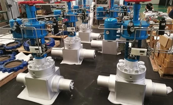
Labyrinth seal was normally designed for high pressure control valve.Control valve is a very import part in power plant pipeline, there are many China high pressure control valve suppliers focus on control valve design ,and some China 2500LB control valve manufacturers have good experience on high pressure control valve