+86 512 68781993


Principles for the Installation and Selection of Valves in Chemical Plants
Principles for the Installation and Selection of Valves in Chemical Plants
This regulation applies to chemical process systems. The valves mentioned do not include safety valves, steam traps, sampling valves, or pressure reducing valves, but do include the installation of flow restrictors, blind flanges, and other piping components with similar functions to valves, collectively referred to as shut-off valves. The function of shut-off valves is to isolate fluids or change their flow direction, and their installation should be based on the requirements of production (including normal operation, start-up and shutdown, and special conditions), maintenance, and safety, while also considering economic feasibility.
Valve setting and selection of the appropriate category (not model). Selecting valves is an important task for process system professionals when preparing P&ID diagrams. The content outlined in this regulation takes into account general production and safety requirements. When system professionals refer to this regulation for engineering design, they should make decisions based on the specific conditions of the project, local weather conditions, inter-plant cooperation, operational requirements of the installation, fluid characteristics, special user requirements, and economic considerations.
Selection of valve categories in engineering design
Factors to consider when selecting
The selection of valves is based on a comprehensive balance and comparison of operational, safety, and economic rationality, resulting from experience. The following original conditions must be provided before selecting a valve:
1.Physical properties
(1) Material State a. For gaseous materials, the state includes relevant physical property data, whether it is a pure gas or a mixture, the presence of droplets or solid particles, and whether it contains components that are prone to condensation. b. For liquid materials, the state includes relevant physical property data, whether it is a pure component or a mixture, the presence of volatile components or dissolved gases (which may form a two-phase flow upon pressure reduction), the presence of solid particulates, and the liquid's viscosity, freezing point, or pour point.
(2) Other Properties: This includes corrosiveness, toxicity, solubility in valve structural materials, flammability, explosiveness, and other related characteristics. These properties can affect not only the material selection but may also impose special structural requirements or necessitate higher pipeline grades.
2.Working conditions under operating status
(1) Working Conditions Under Normal Operation a. Consider the temperature and pressure under normal working conditions, and also take into account conditions during startup, shutdown, or regeneration. For example, the pump discharge valve should account for the maximum shut-off pressure of the pump. b. If the system’s regeneration temperature is significantly higher than the normal temperature but the pressure is reduced, consider the combined effects of temperature and pressure for such systems. c. Continuity of operation: The frequency of valve opening and closing also affects the wear resistance requirements. For systems with frequent switching, consider whether to install double valves.
(2) Allowed Pressure Drop in the System a. If the system allows for a small pressure drop or allows for a larger pressure drop without requiring flow adjustment, choose a valve type with a small pressure drop, such as gate valves or straight-through ball valves. b. If flow adjustment is required, select a valve type with good regulating performance and a certain pressure drop (the proportion of pressure drop to the total pipeline pressure drop and the sensitivity of regulation are related).
(3) Environmental Conditions for the Valve In cold outdoor environments, especially for chemical materials, valve body materials should generally not be cast iron but should be cast steel (or stainless steel).
3.Valve Functions
(1) Cut-off: Almost all valves have a cut-off function. For simple cut-off without flow adjustment, gate valves and ball valves can be used. For rapid cut-off, plug valves, ball valves, and butterfly valves are more suitable. Globe valves can both adjust flow and provide cut-off. Butterfly valves are also suitable for regulating large flow rates.
(2) Changing Flow Direction: Two-way (L-shaped passage) or three-way (T-shaped passage) ball valves or plug valves can quickly change the direction of the flow. Since one valve can perform the functions of two or more straight-through valves, this simplifies operation, ensures accurate switching, and reduces space requirements.
(3) Regulation and Control: Globe valves and plunger valves can meet general flow adjustment needs, while needle valves are used for fine adjustments. For stable regulation over a large flow range (pressure, flow), a throttle valve is more appropriate.
(4) Backflow Prevention: To prevent backflow of materials, a check valve should be used.
(5) Additional Functions: For different production processes, valves with additional functions can be selected, such as those with jackets, drain ports, and bypasses, or valves with blow-off ports to prevent solid particle settlement.
4.Actuation of Switch Valves: Most valves operated locally use handwheels. For valves with certain operational requirements, such as those requiring specific forces or adjustments, alternative actuation methods may be employed.
For valves that are located at a distance, chain wheels or extended rods can be used. Some large-diameter valves have motors integrated into their design due to the high torque required for operation. In explosive environments, corresponding explosion-proof motors should be used.
Remote-Controlled Valves: The types of actuation for remote-controlled valves include pneumatic, hydraulic, and electric. Among electric actuators, there are solenoid valves and motor-driven valves. The choice should be based on the requirements and available energy sources.
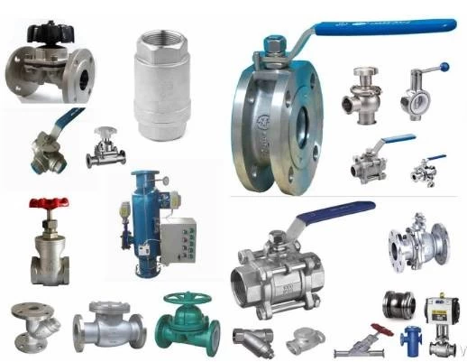
Characteristics and Applications of Various Types of Valves
1. Gate Valve
(1) When fluid flows through a gate valve, it does not change direction. When fully open, the gate valve has one of the lowest resistance coefficients among all valve types and has a wide range of applicable diameters, pressure, and temperature. Compared to a globe valve of the same diameter, its installation size is smaller, making it the most commonly used type in chemical production facilities. (2) Gate valves have two types of handles: rising stem and non-rising stem. The rising stem gate valve is particularly useful for alternating between two or more identical devices, as the rising stem clearly indicates the valve's open or closed status. (3) When the gate valve is partially open, the valve core is prone to vibration, so gate valves are only suitable for fully open or fully closed situations and are not suitable for applications requiring flow adjustment. (4) Gate valves have grooves inside the valve body, so they are not suitable for fluids containing solid particles. Recently, gate valves with blow-off ports have been developed to handle such situations.
2. Globe Valve
(1) Globe valves are widely used in chemical processes. They offer reliable sealing performance and are suitable for flow regulation. They are commonly installed at pump outlets, flow meters upstream of control valves, and other locations where flow adjustment is needed. (2) As the fluid changes direction through the valve core, there is a significant pressure drop, and solid particles may accumulate on the valve seat, making them unsuitable for suspensions. (3) Globe valves are larger in size compared to gate valves of the same diameter, limiting their maximum diameter (typically DN 150–200). (4) Y-type and angle globe valves have smaller pressure drops compared to standard straight-through valves, and angle valves also provide direction-changing functionality. (5) Needle valves are a type of globe valve with a tapered core, suitable for fine flow adjustments or as sampling valves.
3. Plug, Piston, and Ball Valves
(1) These three types of valves have similar functions and can be quickly opened or closed. The valve core has transverse openings, allowing liquid to flow directly through with minimal pressure drop, making them suitable for suspensions or viscous liquids. The valve core can be made with "T" or "L" shaped passages to create three-way or four-way valves. They have a regular shape and can be easily made into jacketed valves for insulation purposes. These types can also be conveniently made into pneumatic or electric valves for remote control. (2) The main difference is that piston and ball valves generally have slightly higher working pressures.
4. Butterfly Valve
Butterfly valves offer some flow regulation functionality and are particularly suitable for large flow adjustments. Their use temperature is limited by the sealing material.
5. Check Valve
(1) Check valves are used to prevent backflow of fluids. They are typically used to avoid contamination, temperature rise, or mechanical damage due to reverse flow. (2) Common types include swing check, lift check, and ball check valves. Swing check valves have larger diameters than the other two types and can be installed on horizontal or vertical pipes (with upward flow in vertical pipes). Lift and ball check valves have smaller diameters and can only be installed on horizontal pipelines. (3) Check valves are only effective in preventing sudden backflow and may have less effective sealing. For materials that strictly require non-mixing, additional measures should be taken. (4) When the centrifugal pump inlet is in a suction state, a bottom valve installed at the inlet pipe end also serves as a check valve to maintain the liquid inside the pump. When the container is open, the bottom valve can be equipped with a filter screen.
6. Diaphragm and Pipe Clamp Valves
These valves ensure that the fluid only comes into contact with the diaphragm or hose, without touching other parts of the valve body. They are especially suitable for corrosive fluids, viscous liquids, or suspensions. However, their usage is limited by the material of the diaphragm or hose.
Valve Placement at Boundaries
At the boundaries of process and utility material pipelines within a plant (usually on the inside of the plant boundary), cut-off valves should be installed, with the following exceptions:
(1) Exhaust systems. (2) Vent pipes for emergency discharge tanks located outside the boundary. If valves must be installed in these cases, they should also be sealed with lead (C.S.O). (3) Pipelines that do not cause cross-contamination or accidents. (4) Pipelines where measurement is not required.
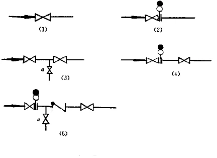
Valve placement at boundaries is illustrated in various ways in Figure 1.2. Among them:
(1) Is suitable for general material cut-off. (2) (4) (5) Should be used when preventing internal leakage of valves is crucial due to potential safety hazards like explosions or fire, or to prevent critical product quality issues. Blinds are added to valves to ensure no leakage. (3) and (5) Are suitable for cases where purging upstream or downstream is required after material feeding. Valve "a" can be used for purging, draining, and leakage inspection, and measurement instruments can be installed between two valves in series. (5) Is suitable for locations where pressure fluctuations may be significant, as a check valve can provide instantaneous cut-off.
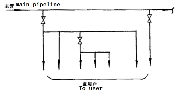
Placement of Root Valves
When a medium needs to be delivered to multiple users, a root valve should be installed close to the main pipe in addition to the cut-off valve near the equipment. This root valve facilitates maintenance, energy saving, and frost prevention. It is commonly used in utility material systems (e.g., steam, compressed air, nitrogen, etc.). The same setup is required when a process material (e.g., solvent) is supplied to multiple users. The valve shown in Figure 1.3 is an example of a root valve.
In pressure pipelines, root valves should be placed as close to the main pipe as possible when energy saving and frost prevention are necessary. All utility material branch pipelines in chemical facilities should have root valves to avoid plant or plant-wide shutdowns due to individual valve failures. For steam and overhead water pipelines, even if they only supply a single device or piece of equipment, a root valve should be added if the branch pipe exceeds a certain length to reduce dead zones, lower energy consumption, and prevent freezing.
For more than one standby steam-using device, the need for separate branch pipe root valves should be determined based on their importance in production. The root valves for utility material branch pipes should be designed by the pipeline engineering team, and the process engineering team should verify the appropriateness of the branches. Root valves should be indicated on the utility material P&ID (distribution diagram).