 +86 512 68781993


Piping layout design principles, basic requirements and selection of compensators
Necessary conditions for piping layout design
National and industry laws and regulations, design standards and regulations that should be complied with
Uniform regulations on engineering design
Process flow (system) diagram
Equipment layout
Equipment table, equipment diagram
Design conditions of relevant specialties (general plan topographic map, plant building drawing, electrical cables, professional piping layout drawing for water supply and drainage, etc.)
Commonly used standards, regulations and specifications for piping layout design
"Code for Design of Industrial Metal Piping" GB50316-2000)
"Code for Design of Industrial Equipment and Pipeline Insulation Engineering" (GB50264-2013)
"Code for Fire Protection Design of Petrochemical Enterprises" (GB50160-2008)
"Code for Fire Protection Design of Buildings" (GB50016-2014)
"Classification of Hazard Degree of Occupational Exposure to Toxic Substances" (GBZ230-2010)
"Code for Design of Urban Gas" (GB50028-2006)
"Code for Design of Urban Heating Power Network" (CJJ34-2002)
"Code for Design of Urban Direct Buried Heating Pipeline Engineering" (CJJ/T81-98)
"Code for Design of Small Thermal Power Plants" (GB50049-2011)
"Technical Regulations for Thermal Power Plant Design" (DL5000-2000)
"Technical Regulations for the Design of Steam and Water Pipelines in Thermal Power Plants" (DL/T5054-96)
"Design Regulations for Insulation Paint in Thermal Power Plants" (DL/T5072-2007)
"Technical Regulations for Chemical Design of Thermal Power Plants" (DL/T5068-2006)
"Design Rules for Gas-Steam Combined Cycle Power Plant" (DL/T5174-2003)
"Code for Design of Boiler Room" (GB50041-2008)
"Code for Design of Producer Gas Station" (GB50195-2013)
"Code for Design of Compressed Air Station" (GBJ29-2014)
"Code for Design of Oxygen Station" (GBJ50030-2013)
"Code for Design of Oxygen Hydrogen Station" (GB50177-2005)
"Code for Design of Acetylene Station" (GB50031-91) 2007 Edition
"Code for Design of Petrochemical Metal Pipeline Layout" (SH3012-2011)
"Code for Design of Gas Transmission Pipeline Engineering" (GB50251-2003)
"Code for Design of Oil Pipeline Engineering" (GB50253-2014)
"Design Rules for Electrostatic Grounding of Chemical Enterprises" (HGJ28-90)
Principles of indoor piping layout
1. Try to avoid the influence of pipelines on indoor lighting, and should not hinder the opening and closing of windows;
2. It should not affect the operation and maintenance of the equipment (such as pipe inspection and equipment lifting);
3. In areas where there are many crossings of horizontal pipelines, generally according to the direction of the pipelines, the vertical and horizontal elevation ranges are delineated, and the pipelines are arranged in layers;
4. The thermal pipeline is generally arranged above the oil pipeline. When it needs to be arranged below the oil pipeline, reliable isolation measures should be taken for the thermal pipeline below the valve, flange or possible oil leakage of the oil pipeline;
5. The pipeline in the trench should be arranged in a single layer as much as possible. When a multi-layer arrangement is adopted, generally small pipes or pipes with high pressure and many valves are arranged on top;
6. Corrosive medium pipelines should not be arranged above pedestrian passages and rotating equipment;
7. Pipelines for Class B fluid media shall not be installed in poorly ventilated factory buildings, indoor ceilings or interlayers;
8. Pipelines for Class B fluid media should not be arranged next to or above high-temperature pipelines;
Layout principles of outdoor pipe network
1. The laying of pipelines in the factory area should be coordinated with the roads, buildings, structures, etc. in the factory area to reduce the intersection of pipelines, railways and roads;
2. Large-diameter pipes should be arranged close to the pipe rack columns;
3. The high-temperature pipeline that needs to be equipped with a "π" type compensator should be arranged near the column;
4. Heat pipes, instruments and electrical cable troughs should be arranged on the upper layer of the pipe rack, and process pipes and corrosive medium pipes should be arranged on the lower layer;
5. For the design of the pipeline on the pipe rack, 10-20% margin should be reserved;
6. When Class B fluid medium pipelines are laid in parallel or crosswise with cables and oxygen pipelines, the clear distance should meet the specification requirements;
7. Class B fluid medium shall not pass through buildings that have nothing to do with it;
8. Class B gas pipelines with higher density than ambient air should not be laid close to the doors and windows of buildings when they have flanges, threaded connections or packing structures;
9. There should be no components that may leak, such as valves, flanges, threaded joints, and compensators with packing, on the pipelines above roads and railways;
10. The floor spacing of the pipe gallery and the net distance of the pipes should meet the installation and operation requirements;
11. For steam pipes or condensable gas pipes, the branch pipes should be connected from the top of the main pipe, and the steam condensate pipe should be connected to the top of the recovery main pipe
Pipeline Thermal Compensation
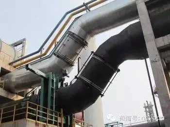
The medium transported by some pressure pipelines often has the characteristics of high temperature and high pressure or due to the change of working environment temperature, the thermal expansion and contraction of metal materials are caused. The pipeline layout design should fully consider the absorption of thermal displacement. Once improperly arranged, some parts of the pipeline will be damaged due to excessive thermal stress, or excessive thrust will be generated on the support, which will affect the safety of the pipeline support, thereby affecting the normal operation of the pipeline system.
Example: The picture shows a pipe connecting two heat exchangers in a factory, the working pressure P=4.0MPa, working temperature t=316, the outer diameter of the pipe is φ219, the center distance of the heat exchanger is 2.1m, and the middle connecting pipe is horizontal. At a distance of 2m, there is a reducing pipe DN200/DN150 at A. The design and installation dimensions of the pipe are shown in the figure.

Operating status: Cracks appear many times in the weld seam at the connection between the reducer and the flange.
Analysis of the cause: due to the close arrangement of the equipment, the intermediate connecting pipe is short, the pipe diameter is large, the flexibility is poor, and the ability to absorb thermal expansion and deformation is small. After the flexibility analysis of the piping system, A is subject to a large lateral thrust and thrust moment
Measures: Due to the limitation of the site, it is impossible to change the length of the pipe, so the pipe diameter has to be changed, and the different-diameter pipe joint is moved from A to B. The outer diameter of the pipe AB is reduced from 219mm to 159mm, so that the flexibility of the pipe is improved. At the same time, the location of the stress concentration at the connection between the reducer and the pipe due to the sudden change in shape also moves from the higher stress area to the lower stress area. In this way, the maximum stress value of the pipeline is reduced, and after several years of production tests, satisfactory results have been obtained.
Piping Vibration:
Hazard: Piping vibration is a common phenomenon. Severe vibration will accelerate crack growth and threaten the safety of the system. Vibration of pipelines connected with equipment, especially those connected with reciprocating machinery, is inevitable, but must be controlled within a certain range.
Causes: The reciprocating motion and vibration of the equipment cause the vibration of the pipeline connected to the equipment (such as compressors, steam turbines, pumps, fans, etc.); resonance is easy to occur with medium pulsation or pressure fluctuations (such as piston compressors, changes in medium flow or Changes in working conditions, etc.); unstable two-phase flow (such as poor drainage of steam pipes), liquid hammer (sudden opening and closing of valves), earthquakes, wind, etc. will aggravate the vibration of the pipeline.
Preventive measures:
Prevent the transmission of equipment vibration, such as a soft joint at the joint
Increase the buffer tank to ensure the stability of the medium; for example, reduce the number of elbows in the pipeline connected to the compressor, and appropriately add pipeline supports to increase stability;
Ensure installation slope, increase water drainage, avoid two-phase flow, and prevent water impact.
Pipe support, component layout safety
Bracket (seat) safety
The bracket (seat) is mainly used to support the weight, stabilize the piping system, limit the displacement (degree of freedom) of the piping, and shock-proof and shock-absorbing. Therefore, the pipeline layout design should be reasonably arranged according to the type, characteristics and safety requirements of the medium to be transported, and the proper structure of the support and hanger should be correctly selected to improve the stress distribution of the pipeline and ensure the safe operation of the pipeline. The support and hanger design can be determined according to the calculation of the pipeline design and structural strength design software or selected according to the relevant design manual.
Piping component quality and layout safety
Piping components include pipes, tees, elbows, reducers, valves, flanges, gaskets, filters, compensators, etc., and their selection and design requirements are introduced in the chapter on piping materials. Here we only introduce what considerations should be made in terms of the arrangement of pipe fittings.
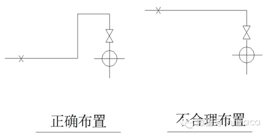
Layout principle of pipeline components: it should be arranged in the place with small deformation displacement and low stress as much as possible.
Valve arrangement: The arrangement on the left is better than that on the right.
compensator arrangement
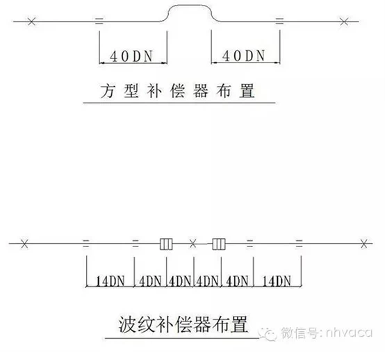
For the Π-type compensator, it is generally required to be arranged in the center of the pipe section between two fixed points, and a guide bracket should be provided at an appropriate position to facilitate the absorption of thermal displacement; for the general-purpose corrugated compensator, it is required to be arranged next to the fixed bracket, and according to The manufacturer requires a certain guide bracket to ensure the stability of the compensator. Refer to the figure below for the bracket setting requirements:
Effects on connected devices:
The force and torque of the pipeline on the connected equipment should comply with the regulations allowed by the equipment manufacturer. If it exceeds the regulations, it will affect the safety of the equipment and cause leakage at the connecting flange.
measure:
A support and hanger is provided at the connection of the equipment to bear the weight of the pipe and the thrust of the pipe end, as shown in the figure below.
Improve the flexibility of the pipeline at the connection, such as a flexible joint or a flexible elbow. If a general-purpose corrugated compensator (or soft joint) is installed, attention must be paid to the influence of the blind plate force. As shown in the picture:

Pipeline safety distance and laying method
The intersecting relationship and safety distance of various pipelines such as heat, electricity, and flammable and explosive fluid media should be arranged in strict accordance with the requirements of regulations and specifications, and effective measures should be taken if they cannot be satisfied. Whether the pipeline is laid properly or not will also affect the safety of the pipeline. For example, the Class B fluid medium pipeline should not be arranged in the trench without safety measures (especially like the liquefied gas pipeline that is heavier than air).
Valves are also a very important devices in pipeline installation. Such as some forged valves (titanium check valve) and large size casting valves.