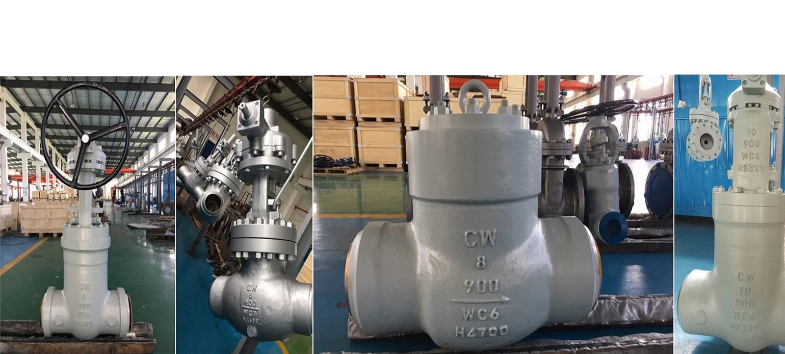
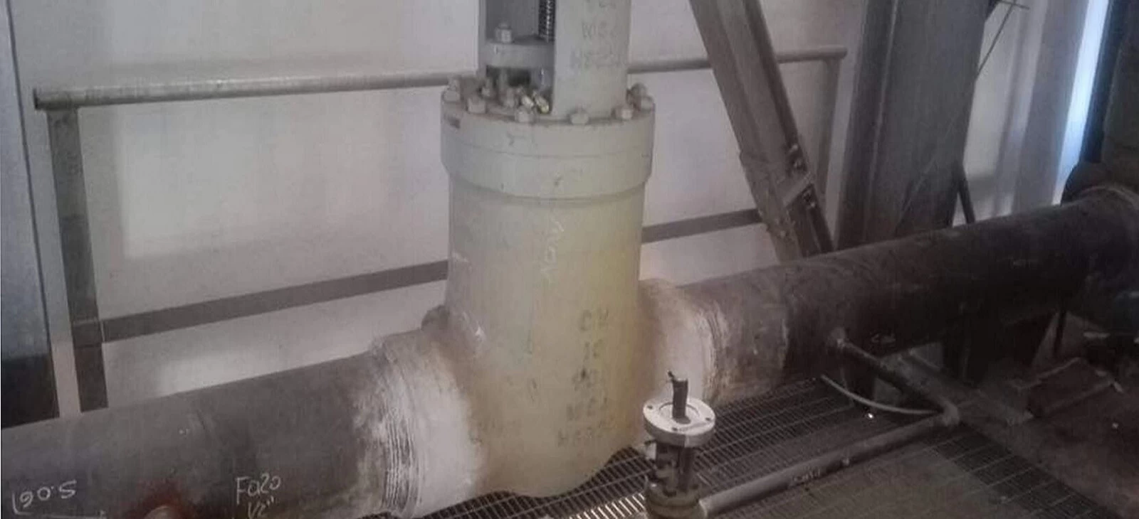
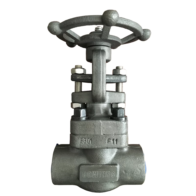
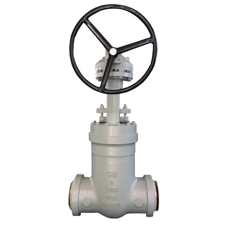
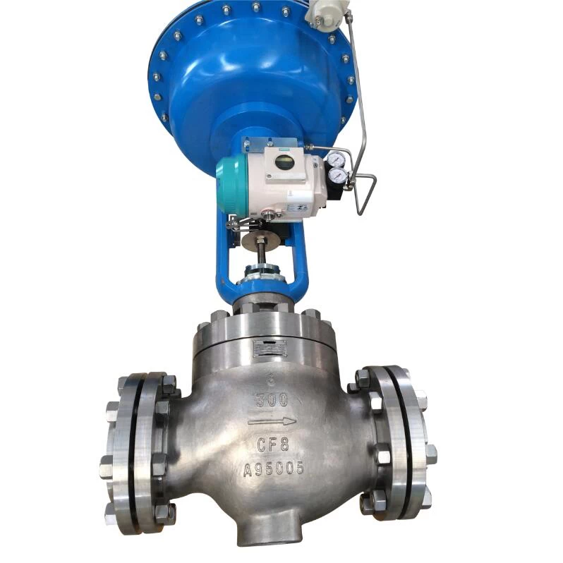
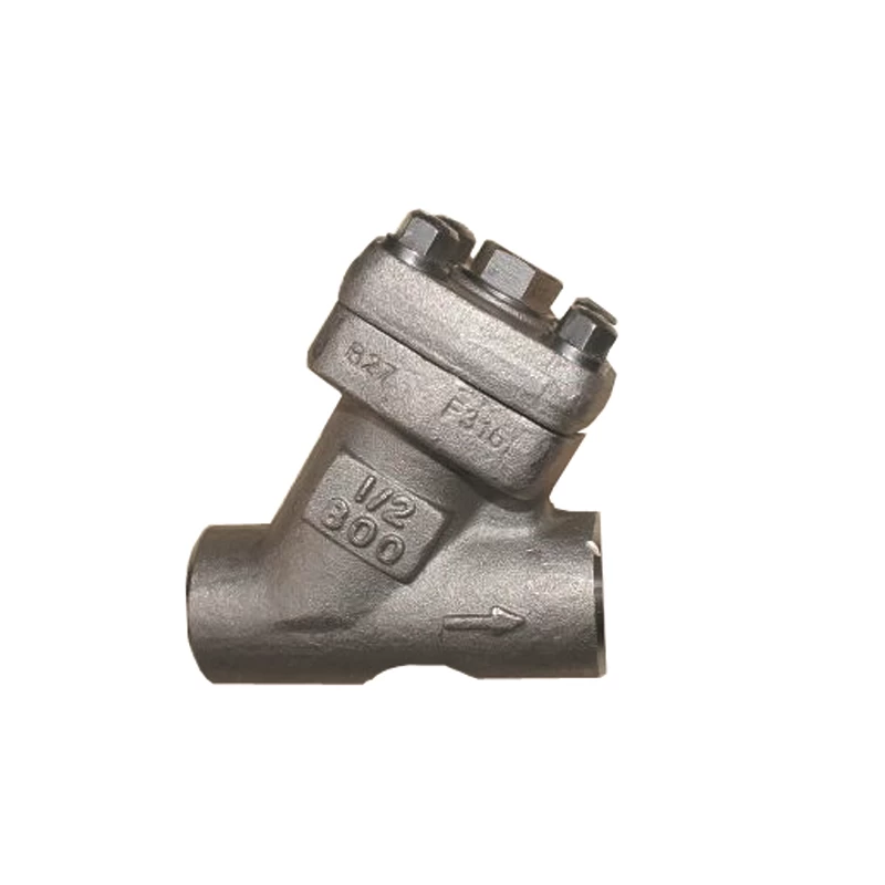
Brief functions of pipeline valves
In the piping system, the valve is acontrol element, just like a human hand, so its importance is self-evidentwhether in life or in all walks of life.
What are its functions? how to install?What does the common logo mean? What should I do if something goes wrong? Themost important 4 aspects, next, let's learn it!
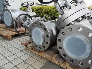
Four functions:
1.Cut-off and open media
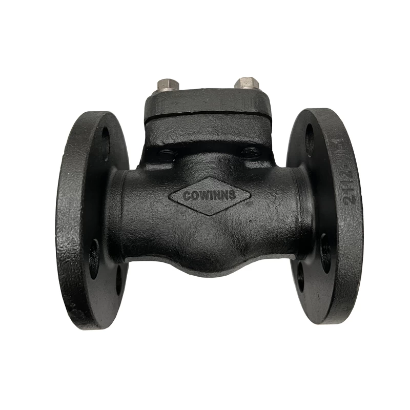
The flow channel is a straight-throughvalve with a small flow resistance. It is usually selected as a valve forclosing and opening the medium.
Down-closed valves (stop valves, plungervalves) are less commonly used due to their tortuous flow paths and higher flowresistance than other valves. Where higher flow resistance is allowed, a closedvalve can be selected.
2. Control flow
Generally, a valve that is easy to adjustthe flow rate is selected for controlling the flow rate. Down-closed valves(such as globe valves) are suitable for this purpose because their seat size isdirectly proportional to the travel of the closure.
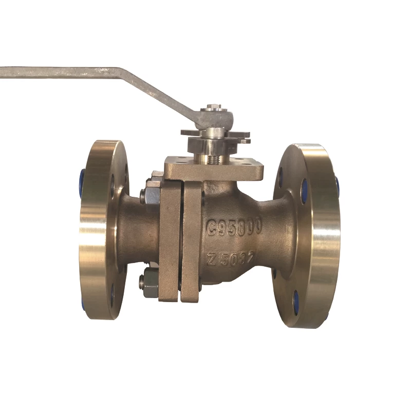
Rotary valves (plug valves, butterflyvalves, sea water butterfly valve, ball valves) and flexure valve (clampvalves, diaphragm valves) can also be used for throttling control, but usuallyonly applicable to a limited range of valve calibers.
The gate valve uses a disc-shaped gate tomake a cross-cutting motion to the circular valve seat. It can only control theflow better when it is close to the closed position, so it is usually not usedfor flow control.
3. Commutation shunt
This valve can have three or more channelsdepending on the need for reversing and diverting. Plug valves and ball valvesare more suitable for this purpose, so most of the valves used for reversingand diverting use one of these valves.
However, in some cases, other types ofvalves can be used for reversing and diverting as long as two or more valvesare properly connected to each other.
4. Medium with suspended particles
When suspended particles are contained inthe medium, it is most suitable to use a valve with a wiper function whosesliding member slides along the sealing surface.
If the back-and-forth movement of theclosing member to the valve seat is vertical, then particles may be trapped, sothis valve is only suitable for basically clean media unless the sealingsurface material allows the particles to be embedded. Ball valves and plugvalves have a wiping effect on the sealing surface during the opening andclosing process, so they are suitable for use in media with suspendedparticles.
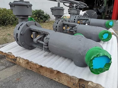
Three major installation issues
1.Check before installation
1). Carefully check whether the valve modeland specifications meet the requirements of the drawing.
2). Check whether the valve stem and valveflap are opened flexibly, and whether they are jammed or skewed.
3). Check the valve for damage and whetherthe thread of the threaded valve is straight and complete.
4). Check whether the valve seat and valvebody are firmly connected, the valve disc is connected to the valve seat, thevalve cover and the valve body, and the valve stem is connected to the valvedisc.
5). Check whether the valve gasket, packingand fasteners (bolts) are suitable for the requirements of the nature of theworking medium.
6). Old or long-standing pressure reducingvalves should be dismantled, and dust, sand and other debris should be washedaway with water.
7). Remove the port cover and check theseal. The valve flap must be closed tightly.
2. General requirements for installation
1). The valve installation position shouldnot hinder the operation, disassembly, repair and maintenance of the equipment,pipelines and the valve body itself, while taking into account the beautifulappearance of the assembly.
2). For valves on horizontal pipelines,install the valve stem upward or install it at an angle. Do not install it withthe handwheel downwards. Valves, stems and handwheels on high-altitudepipelines can be installed horizontally, and the opening and closing of the valvescan be controlled remotely with a chain at a low level.
3). The arrangement is symmetrical, neatand beautiful; the valve on the riser is the most suitable to operate with thechest height of the valve, if the process permits, it is generally 1.0-1.2m awayfrom the ground, and the valve rod must be along the operator Orientation.
4). The center line elevation of the valveson side-by-side risers should preferably be the same, and the clear distancebetween the handwheels should not be less than 100mm; the valves onside-by-side horizontal pipes should be staggered to reduce the distancebetween pipes.
5). When installing heavy valves on waterpumps, heat exchangers and other equipment, a valve bracket should be provided;when the operation is frequent and the valve is more than 1.8m away from theoperating surface, a fixed operating platform should be provided.
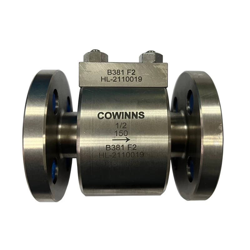
6). If there is an arrow mark on the valvebody, the direction of the arrow is the flow direction of the medium. Wheninstalling the valve, pay attention that the arrow points in the same directionas the medium flow in the pipe.
7). When installing flange valves, ensurethat the two flange end faces are parallel and concentric with each other. Donot use double gaskets.
8). When installing a threaded valve, forease of disassembly, a threaded valve should be equipped with a live joint. Theinstallation of live joints should consider the convenience of maintenance.Usually, the water flows through the valve first and then through the live joints.
3. Installation Precautions
1). The valve body material is mostly madeof cast iron and C95800 lug wafer butterfly valve, which is brittle, so it mustnot be hit by heavy objects.
2). When carrying the valve, it is notallowed to throw it by hand. When lifting or lifting the valve, the rope shouldbe tied to the valve body. It is strictly forbidden to be tied to thehandwheel, valve stem and flange bolt hole.
3). The valve should be installed in themost convenient place for operation, maintenance and repair, and it is strictlyprohibited to bury it underground. Valves on pipelines in direct burial andtrenches shall be equipped with inspection wells to facilitate valve openingand closing and adjustment.
4). The thread should be intact andtangled, leaded with oil or wrapped with PTFE raw material tape. When twisting,you need to use a wrench to clamp the hexagonal valve body screwed into one endof the pipe.
5). When installing a flanged valve, payattention to tightening the connecting bolts diagonally, and use even forcewhen turning to prevent the gasket from drifting or causing deformation anddamage to the valve body.
6). The valve should be kept closed duringinstallation. For threaded valves closer to the wall, the valve stem disc andhandwheel need to be removed during installation to be able to rotate. Whendisassembling, turn the handwheel to keep the valve open, and then disassemble.
 +86 512 68781993