+86 512 68781993


Operation and Maintenance Manual for Pneumatic Control Valve Repair
Operation and Maintenance Manual for Pneumatic Control Valve Repair
1. General Provisions
1.1 Main Content: This repair operation and maintenance manual specifies the daily maintenance, troubleshooting, safety precautions, and specific technical requirements and implementation steps for pneumatic control valves used in-line. It also provides guidance that can be referenced for other types of control valves.
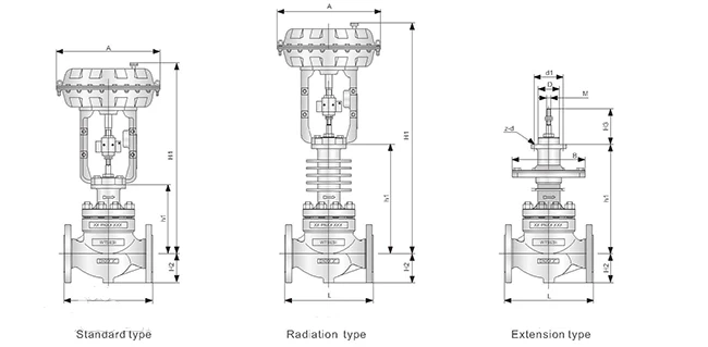
1.2 Basic Composition: The pneumatic control valve consists of two main components: the pneumatic diaphragm actuator and the valve body parts. The actuator is made up of the upper and lower diaphragm covers, corrugated diaphragm, tray, bracket, push rod, spring, adjustment components, and other parts. The valve body part consists of the valve body, valve core, valve seat, valve stem, flanges, and other components.
1.3 Working Principle of Pneumatic Control Valve: When the signal pressure is input into the diaphragm air chamber, a thrust is generated on the corrugated diaphragm, which moves the push rod and compresses the spring until the force from the spring balances the thrust. The movement of the push rod corresponds to the stroke of the pneumatic actuator. There are two types of actuator action modes:
- Direct Action: When the signal pressure increases, the push rod moves downward.
- Reverse Action: When the signal pressure increases, the push rod moves upward.
1.4 Types of Control Valves: According to their structural form, control valves can be classified into:
- Straight-through single-seat valve
- Straight-through double-seat valve
- Angle valve
- Three-way valve
- Diaphragm valve
- Butterfly valve
1.5 Scope of Application: This repair operation and maintenance manual is applicable to all instrument personnel in the Instrumentation Workshop of the Electrical and Instrumentation Department.
2. Purpose of Repair
The purpose of the repair is to ensure that the control valve is in good working condition, with no internal leakage, no sticking, and with smooth and flexible opening and closing actions. All connection points should be leak-free, allowing the valve to effectively regulate and control the medium within the pipeline and equipment at any position. This ensures the stable operation of the production process.
3. Preparations Before Repair
3.1 Personnel Division of Work:
1. Repair Leader: Based on the fault symptoms of the instrument components, the repair leader will determine the repair tasks, ensure the repair quality, and confirm whether the replacement parts are of acceptable quality. The replacement valve positioners and other components must be suitable for the specific control position. The repair leader is responsible for ensuring that the repaired or replaced valve is in optimal condition and that the repair work is completed with high quality and on schedule.
2. Safety Leader: The safety leader is responsible for supervising safety during the repair work, ensuring that safety measures are fully implemented, protective equipment is ready and worn properly, and reminding the repair leader of safety precautions during the repair process. The safety leader ensures that the safety measures are in place, ensuring the repair work can be completed safely and smoothly.
3.2 Working Time: [The specific working time should be added based on the actual situation.]
3.3 Repair Tools:
- 2 adjustable wrenches (12 inches)
- Pliers
- Screwdrivers
- Electrical tape
- Fine sandpaper
- Signal generator
3.4 Repair Spare Parts:
- Control valve
- Valve positioner
- Diaphragm
- Spring
- Related accessories
3.5 Required Documentation:
- Repair notification
- Repair task list
- Process handover sheet (based on the actual situation)
- Working at height certificate (if applicable)
4. Requirements During the Repair Process:
4.1 Spare Parts Preparation:
Ensure that the required spare parts are available. The spare parts must match the specifications, model, material, nominal pressure, and function (direct or reverse action) of the control valve and its components being replaced or repaired.
4.2 Tool Preparation:
Ensure that all tools are suitable, in good condition, and complete.
4.3 Documentation:
Ensure that all required documentation is completed. Work can only proceed after obtaining approval from the dispatchers, operators, and other relevant personnel.
4.4 Confirmation Before Dismantling:
Before disassembling the control valve or its components, confirm that the process treatment has been properly completed and ensure that the operators are present to supervise the site.
4.5 Repairing the Valve Positioner and Components:
When repairing the control valve positioner or other components, the operator must first close the upstream and downstream valves of the control valve tightly. After the operator stabilizes the process with bypass valves and confirms that the process conditions are stable, the operator should agree, and both the operator and the repair leader must confirm that the process treatment is qualified. Ensure that the control valve's opening and closing actions do not affect production and that no residual medium or pressure remains inside the valve before proceeding with the repair and adjustment.
4.6 Disassembling the Control Valve:
Before disassembling the control valve, wear appropriate protective equipment such as a gas mask and gloves. Begin by loosening the connecting bolts in a diagonal pattern. Slowly loosen the flange between the valve body and the pipeline until a gap is created. Ensure that there is no medium pressure left inside the valve before proceeding with disassembly.
4.7 Installing the Control Valve:
When installing the control valve, ensure that the arrow on the valve body matches the direction of the medium flow. When replacing small-diameter valves with threaded connections, detachable connectors must be used. The control valve should be securely fixed.
4.8 Calibration of Ordinary Positioner:
- Connect the air supply to the diaphragm actuator through an air filter and regulator. Adjust the air pressure to position the actuator’s push rod in the middle of its full stroke.
- When the push rod is positioned at the center of its full stroke, adjust the positioner so that the feedback rod is perpendicular to the positioner.
- Connect the air supply to the input of the positioner’s regulator and filter, and connect the positioner’s output to the diaphragm chamber.
- Input a 4mA signal and turn the zero adjustment screw to start the actuator.
- Increase the signal to 20mA to fully extend the actuator. If the stroke is insufficient, loosen the stroke adjustment locking screw, adjust, and then tighten the locking screw.
- Repeatedly adjust until the actuator’s end points are within the permissible error range.
4.9 Calibration of Intelligent Positioner:
- Set the input signal for the AVP (positioner) to DC 18±1mA.
- Using a flathead screwdriver, rotate the zero-to-full-scale adjustment screw clockwise until it can no longer turn (90°).
- Hold this position until the valve begins to operate (approximately 3 seconds), and then start the automatic setup program.
- The valve will move from fully closed to fully open twice, then stop at the 50% position and remain there for 3 minutes.
- Change the input signal to confirm that the automatic setup is complete. The entire process takes about 3 minutes.
- If the input signal drops below 4mA during the automatic setup, the process will fail and needs to be restarted. After completing the automatic setup, maintain a signal of at least 4mA for at least 30 seconds to ensure that the data and parameters are saved in the AVP's EEPROM.
4.10 Inspection During Valve Disassembly:
Pay particular attention to signs of corrosion or wear on the valve body, valve seat, valve core (or stem), and other components. Inspect the diaphragm or O-rings in the actuator for aging or damage. Check the sealing of the packing and other accessories. Replace any severely damaged parts.
4.11 Post-Calibration Check:
After calibrating the control valve, ensure that the scale and valve position indicator are consistent at all valve openings.
5. Quality Requirements for the Repair:
- The repaired or replaced control valve and accessories should be installed according to proper standards and securely fixed.
- No leaks should be present at any connections.
- The valve should operate smoothly and flexibly with stable action.
- Zero points and range adjustments should meet operational requirements, and the indicator should be accurate.
- Spare parts should be complete, materials should be correct, and all components should be clean.
- Proper calibration and maintenance records should be kept, with waterproofing measures in place.
6. Post-Repair Requirements:
6.1 Site Cleanup:
After completing the repair, clean the site promptly to ensure that the work area is tidy and all materials are accounted for.
6.2 Post-Repair Valve Check:
The operator should open the upstream and downstream valves and check for any leaks at the connections. The control valve should be fully operational and ready for use.
7. Daily Inspection and Maintenance:
7.1 Visual Inspection:
- Check the external appearance of the control valve for any leaks at the connections, loose components, or missing accessories.
7.2 Signal Wire Check:
- Inspect the signal wires for any looseness or wear.
7.3 Air Leakage Check:
- Inspect the cylinder or diaphragm head for air leakage, and check if there are any leaks at the threaded connections.
7.4 Lubrication:
- Regularly lubricate moving parts and bolts to prevent corrosion.
7.5 Calibration and Inspection:
- Perform calibration and inspection whenever the opportunity arises.
7.6 Protection Pipe Inspection:
- Check the integrity of protective pipes and ensure waterproof measures at cable entry points are intact.
7.7 Positioner Maintenance:
- Inspect the valve positioner's air supply filter and regulator diaphragm for cleanliness. Drain the air supply ball valve and air supply line every six months.
7.8 Pressure Gauge Check:
- Ensure that air pressure gauges are functioning correctly and provide accurate readings.
8. Troubleshooting
(1) Valve Body Erosion
Possible Causes:
- ① High fluid velocity
- ② Presence of particles in the fluid
- ③ Cavitation and flashing
Treatment Methods:
- ① Increase the size of the valve body internals to reduce fluid velocity
- ② Modify the valve body to a streamlined design to reduce fluid impact
- ③ Use materials with increased hardness for the valve body
- ④ Alter the internal valve structure to reduce fluid velocity
- ⑤ Prevent cavitation by using a valve designed for low-pressure recovery
- ⑥ Weld repair with stainless steel materials
(2) Erosion of Valve Internals
Possible Causes:
- ① High fluid velocity
- ② Presence of particles in the fluid
- ③ Cavitation and flashing
Treatment Methods:
- ① Increase the size of the valve or valve internals to reduce fluid velocity
- ② Use harder valve internals
- ③ Change the valve internal structure to reduce fluid velocity
- ④ Avoid cavitation by using valves and valve internals designed for this purpose
- ⑤ Use a streamlined design to prevent impact
(3) Leakage Between Valve Plug and Seat
Possible Causes:
- ① Poor condition of the valve plug or seat surface (wear, corrosion)
- ② Insufficient actuator force
- ③ Corrosion or loosening of the valve seat thread
Treatment Methods:
- ① Improve the contact surfaces (seal faces)
- ② Adjust the actuator and valve stem connection bracket
- ③ Tighten or repair/replace the valve plug or seat
Other issues to be checked during routine maintenance include:
- Leakage between the seat ring and valve body
- Packing leakage
- Leakage between the upper valve cover and valve body
- Disconnection or breakage of the valve stem
- Valve not reaching its rated stroke
- Slow or sluggish valve operation or movement
9. Safety Precautions During Repair
9.1 Work Conditions:
- Ensure the correct working conditions are used: the air supply must be dry, oil-free, dust-free, and kept clean.
9.2 Medium Temperature:
- Ensure that the medium temperature is within the operating range for the control valve especially for high pressure control valve.
9.3 Flow Direction and Pressure Differential:
- Correctly select the flow direction and verify the upstream and downstream pressure differential.
9.4 Approval for Repair:
- Instrumentation personnel must obtain approval from the operators and complete all necessary documentation before proceeding with the repair or calibration of the control valve.
9.5 Disassembly and Inspection:
- When disassembling the valve body for inspection, ensure that the upstream and downstream shutoff valves are confirmed to be closed by the operators before starting the disassembly.
10. Common Faults
10.1 A Pneumatic Valve Fails to Fully Close During Operation:
Possible Causes:
- ① Severe wear between the valve plug and seat
- ② Leakage in the actuator diaphragm
- ③ Foreign objects stuck between the valve plug and seat
- ④ Excessive pressure differential across the valve
- ⑤ Excessive preload on the zero-point spring
- ⑥ The positioner output cannot reach the maximum value
- ⑦ The valve stem is too short
10.2 Effect of Feedback Rod Disconnection in the Positioner and Valve Stem:
When the feedback rod that connects the positioner to the valve stem is disconnected, the positioner loses its feedback and behaves like a high-gain pneumatic amplifier.
- If the positioner is of the **direct action** type, when the signal increases, the output will also increase, and the valve stem will run to its maximum output.
- If the positioner is of the reverse action type, the output will drop to zero.
10.3 Functions of the Valve Positioner:
The valve positioner has several functions:
- ① Improves the static characteristics of the control valve and enhances the linearity of the valve position.
- ② Improves the dynamic characteristics of the control valve, reducing signal transmission lag.
- ③ Changes the flow characteristics of the control valve.
- ④ Adjusts the valve's response range to signal pressure, enabling segmental control.
- ⑤ Reverses the valve’s action if required.