 +86 512 68781993


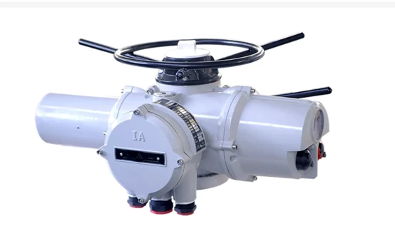
Introduction of valve electric device
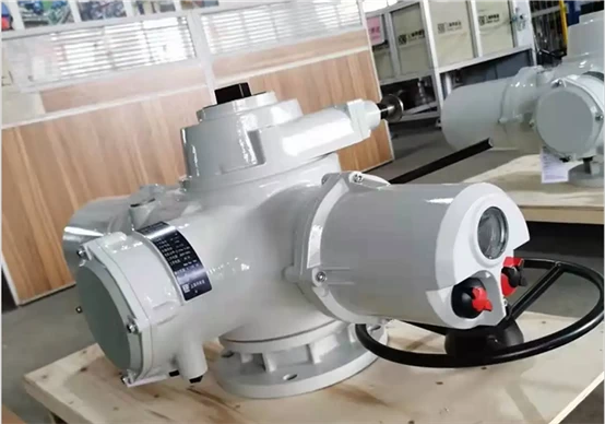
Valve electric device is a device that uses electricity to drive open, close or adjust the valve.
Electric valve electric device is an indispensable driving device for realizing valve program control, automatic control and remote control. Its movement process can be controlled by stroke, torque or axial thrust. The working characteristics and utilization of the valve electric device depend on the type of valve, the working specification of the device and the position of the valve on the pipeline or equipment.
The electric device generally consists of the following parts
Special motor, characterized by strong overload capacity, large starting torque, small moment of inertia, short-term, intermittent operation
Reduction mechanism to reduce the output speed of the motor
Stroke control mechanism to adjust and accurately control the opening and closing position of the valve
Torque limiting mechanism to adjust the torque (or thrust) and keep it from exceeding a predetermined value
Manual, electric switching mechanism, interlocking mechanism for manual or electric operation
Opening indicator to show the position of the valve during opening and closing
Electric actuator selection based on valve type
Angular stroke electric actuator
Rotary stroke electric actuator (rotation angle < 360 degrees) - suitable for butterfly valve, ball valve, plug valve, etc.
The rotation of the output shaft of the electric actuator is less than one revolution, that is, less than 360 degrees, usually 90 degrees to realize the valve opening and closing process control. This type of electric actuator is divided into two types: direct connection type and base crank type according to the different installation interface methods.
Direct connection type: refers to the form in which the output shaft of the electric actuator is directly connected to the valve stem
Base crank type: refers to the form in which the output shaft is connected to the valve stem through a crank
Multi-turn electric actuator
Multi-turn electric actuator (angle > 360 degrees) - suitable for gate valves, globe valves, etc.
The rotation of the output shaft of the electric actuator is more than one turn, that is, more than 360 degrees. Generally, multiple turns are required to realize the valve opening and closing process control.
Straight stroke
Straight stroke (linear motion) - suitable for single-seat control valve, double-seat control valve, etc.
The motion of the output shaft of the electric actuator is linear motion, not rotational.
Determine the control mode of the electric actuator according to the production process control requirements
Control Mode of Electric Actuator
Switch type (open loop control)
The switch-type electric actuator generally realizes the opening or closing control of the valve. The valve is either in the fully open position or in the fully closed position. This type of valve does not need to accurately control the flow of the medium. It is particularly worth mentioning that the switch-type electric actuator can be divided into a split structure and an integrated structure due to different structural forms. This must be explained when selecting models, otherwise there will often be mismatches such as conflicts with the control system during on-site installation.
1. Split structure (usually called ordinary type): the control unit is separated from the electric actuator.
The electric actuator cannot control the valve alone, and it must be controlled by an external control unit. Generally, the external controller or control cabinet is used for matching. The disadvantage of this structure is that it is inconvenient for the overall installation of the system, increases the cost of wiring and installation, and is prone to failures.
2. Integrated structure (usually called integral type): The control unit and the electric actuator are packaged into one body, which can be operated on the spot without external control unit, and can be operated remotely only by outputting relevant control information. The advantages of this structure are that it is convenient for the overall installation of the system, reduces wiring and installation costs, and is easy to diagnose and troubleshoot. However, the traditional integrated structure products also have many imperfections, so intelligent electric actuators have been produced.
Modulating type (closed loop control)
The regulating electric actuator not only has the function of the switch-type integrated structure, but also can accurately control the valve and adjust the flow of the medium.
1. Control signal type (current, voltage). The control signal of the regulated electric actuator generally has a current signal (4~20mA, 0~10mA) or a voltage signal (0~5V, 1~5
V), the control signal type and parameters should be clearly defined when selecting the model
2. Working form (electric open type, electric close type). The working mode of the regulating electric actuator is generally the electric open type (taking the control of 4~20mA as an example, the electric open type means that the 4mA signal corresponds to the valve closing, and 20mA corresponds to the valve opening), and the other is the electric close type. (Take the control of 4~20mA as an example, the electric open type means that the 4mA signal corresponds to the valve open, and the 20mA corresponds to the valve close)
3. Loss of signal protection. Loss of signal protection means that when the control signal is lost due to line failures, the electric actuator will control the valve to open and close to the set protection value. The common protection values are fully open, fully closed, and remain in place.
Electric devices classified according to use environment and explosion-proof class
According to the use environment and explosion-proof grade requirements, the electric device of the valve can be divided into ordinary type, outdoor type, explosion-proof type, outdoor explosion-proof type, etc.
Determine the output torque of the electric actuator according to the torque required by the valve
The torque required to open and close the valve determines the output torque selected by the electric actuator. Generally, it is proposed by the user or selected by the valve manufacturer. As the actuator manufacturer, it is only responsible for the output torque of the actuator, which is required for the normal opening and closing of the valve. The torque is determined by the valve diameter, working pressure and other factors, but due to the difference in processing accuracy and assembly process of valve manufacturers, the torque required for valves of the same specification produced by different manufacturers is also different, even if the same valve manufacturer produces the same torque. The torque of the valve is also different. When the torque of the actuator is too small, it will cause the valve to be unable to open and close normally. Therefore, the electric actuator must choose a reasonable torque range.
The basis for correct selection of valve drive device
Operating torque:
The operating torque is the most important parameter for selecting the valve electric device, and the output torque of the electric device should be 1.2~1.5 times of the maximum operating torque of the valve.
Operating thrust:
There are two main structures of the valve electric device: one is not equipped with a thrust plate, and the torque is directly output; the other is equipped with a thrust plate, and the output torque is converted into the output thrust through the valve stem nut in the thrust plate.
Number of turns of the output shaft:
The number of turns of the output shaft of the valve electric device is related to the nominal diameter of the valve, the pitch of the valve stem, and the number of thread heads. It should be calculated according to M=H/ZS (M is the total number of turns that the electric device should meet, and H is the valve. Opening height, S is the thread pitch of the stem drive, Z is the number of stem thread heads).
Stem Diameter:
For multi-turn rising stem valves, if the maximum stem diameter allowed by the electric device cannot pass through the stem of the equipped valve, it cannot be assembled into an electric valve. Gate valve, globe valve, ball valve, butterfly valve can be designed with electrical actuator operation, but dual plate check valve is not in this scope. Therefore, the inner diameter of the hollow output shaft of the electric device must be larger than the outer diameter of the stem of the rising stem valve. For part-turn valves and dark-stem valves in multi-turn valves, although the passage of the diameter of the valve stem does not need to be considered, the diameter of the valve stem and the size of the keyway should also be fully considered when selecting, so that the valve can work normally after assembly.
Output speed:
If the opening and closing speed of the valve is too fast, water hammer is easy to occur. Therefore, the appropriate opening and closing speed should be selected according to different use conditions.