 +86 512 68781993


Sealing Technology A Brief History of the Development of ASME M and Y Factors
Sealing Technology - A Brief History of the Development of ASME M and Y Factors
As a leading China titanium parallel gate valve manufacturer, we recognize the importance of ASME (American Society of Mechanical Engineers) gasket factors, which have been applied in the field of flange design for over 80 years. Despite this long history, few are aware of the development story behind these factors. This article will trace back to the earliest applications and provide an in-depth explanation of the evolutionary stages that followed.
The primary source of information for this article is ASME’s publication Pressure Vessel and Piping Design, which includes a series of technical papers written between 1927 and 1959. Additionally, contemporary technical data is incorporated. While the article balances both historical and modern perspectives, it does not discredit either; rather, it highlights the application of relevant ASME factors and introduces today’s more advanced design technologies.

The ASME gasket factors have been widely used in flange design for over eight decades, yet their development history remains relatively unknown. This article aims to uncover the origins and subsequent evolution in detail.
Abstract Concept
The industry consensus holds that under a specific system working pressure, there is a particular proportional relationship between the gasket unit stress required to achieve effective sealing and the system’s operating pressure. This relationship can be defined as the joint pressure ratio, considered a potential defining coefficient useful in flange design.
Authors of ASME publications have specifically noted that, although this concept is abstract, it has been broadly applied in flange design. From this concept, two factors were developed: the initial assembly stress Y (formerly called the yield factor) and the contact ratio (overlap) M. More precisely, these two factors were later recommended as non-mandatory reference data, usable in flange design to estimate bolt loads in two different scenarios.
Limitations
The authors of Gasket Load Constants (published in 1943) pointed out that the above concept has generally had a positive impact when applied in flange design. However, criticisms also exist, mainly addressing the shortcomings revealed in the application of the M and Y factors.
The sealing mechanism of gaskets has not yet been fully elucidated, and factors such as temperature variations of the gasket were not considered in the aforementioned coefficients. The authors at the time acknowledged that “the currently used gasket design rules represent an extremely simplified solution to a complex problem. Only a portion of the most important fundamental effects has been taken into account.”
There were also other comments at the time indicating that experiments showed the M and Y values were not actually constants. Some voices suggested that ASME should publish specific methods to determine the M and Y values, but this was not acted upon.
Points of Confusion
In Gaskets and Bolted Joints (1950), the author pointed out, “What is puzzling is that after reviewing some relevant American technical literature, I found that no paper studied the sealing conditions of bolted joint gaskets through theoretical analysis or experimentation.”
The author of this book also expressed a hope for a formal testing procedure to better define the abstract concept of sealing effectiveness. He further noted that the best way to define joint sealing effectiveness is based on maximum allowable leakage rates, related criteria, and corresponding to specific media.
Years later, this paper contributed to the emergence of the concept of sealing classes. The EN 13555 testing standard categorizes sealing classes as L1.0, L0.1, L0.01, and so forth. The Pressure Vessel Gasket Testing Group categorizes them as Class 1, Class 2, Class 3, etc. Markl objected, stating that the original intent of the design committee introducing the M and Y factors was primarily to improve flange strength design.
Gasket Tightness
Today, formal gasket testing procedures allow scientific analysis of gasket properties and clarify their relationship with operating conditions. Gasket tightness needs to be supported by calculations and data. In Europe, gasket tightness is a key concern in flange joint design, having been incorporated into the basic flange design standard (EN1591-1) as early as 2001.
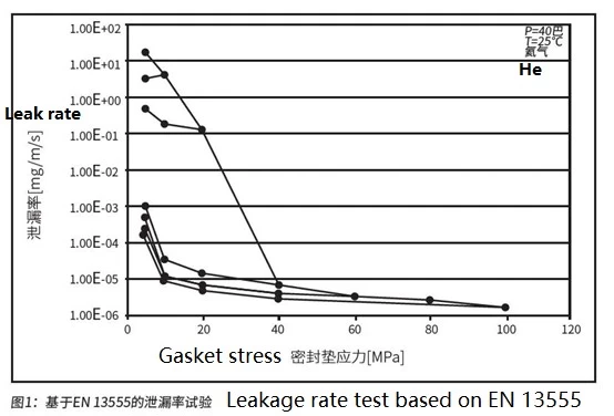
Unfortunately, practices in the United States differ. Although formal gasket tightness testing procedures were introduced over 25 years ago, experts familiar with the field know that the U.S. Pressure Vessel Research Council (PVRC) has provided a tightness-based calculation method for bolt loads on gasketed flange joints (PVRC method). Figure 1 shows test curves based on the EN 13555 standard, demonstrating the gasket stress values corresponding to achieving specific tightness levels.
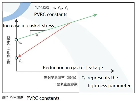
Figure 2 shows the constant relationship graph from the PVRC tests. The figure also illustrates the specific proportional relationship between tightness and gasket stress. Parameters related to tightness include a, GB, and GS, which can represent particular tightness values or classes. The test medium for both Figures 1 and 2 is helium gas. When using other media, adjustments should be made for molecular weight and viscosity accordingly.
Conflict with ASTM Standards
To incorporate tightness-based bolt load parameters into ASME pressure vessel codes, ASME established a special working group. In the third edition of An Introduction to the Design and Behavior of Bolted Joints (copyrighted 1995), the author recommended including the aforementioned tightness-based calculation method into ASME standards in 1995.
Surprisingly, as of 2022, this recommendation has yet to be realized, even though some industry companies have long been familiar with and have applied the tightness-based bolt load calculation method for decades; for the author, this has been over twenty years, not to mention even longer elsewhere.
For engineers, one reason for adopting the tightness-based calculation method is that bolt loads derived from the M and Y factors are not always satisfactory. In some cases, the required load exceeds the values derived from M and Y factors.
Obviously, the tightness-based calculation method conflicts somewhat with existing ASME standards. ASME has recognized this and made corrections in Section VIII, Division 1, Non-Mandatory Appendix S — Design Considerations for Bolted Flange Joints. The committee also acknowledges that bolt loads derived from M and Y factors are insufficient to ensure gasket tightness and leakage rate requirements. An excerpt from the appendix states: “…clearly, when tightening bolts, in some cases it is necessary to use an initial bolt preload higher than the design value…”
Still Unresolved
In summary, the M and Y factors have a positive effect on bolted flange joint tightness and have been in use for many years. However, today a number of engineers use ASME standards while also recognizing the reliability and sealing benefits of tightness-based bolt loads. They find themselves having to decide which standard to follow based on their own judgment. To better understand the relationship between flange leakage rates (and/or tightness) and the M and Y factors, extensive technical research has been conducted in the industry. Unfortunately, the knowledge gained, including efforts from the ASME special working group, has yet to be officially incorporated into the pressure vessel code.
For many ASME flange designers, tightness-based bolt loads remain a vague concept. Moreover, they lack authoritative guidance on which tightness class corresponds to specific media.
Filling the Gaps
Equally awkward is that determining how much the “over-design load” can exceed the design value under specific conditions still relies on the subjective judgment of the designer. It is hoped that these shortcomings will soon be addressed.
With regard to assessing and preventing fugitive emissions, modern technology can — or rather should — handle this effectively. However, the M and Y factors and related calculation methods, prominently listed in EN 13480-3 or EN 13445-3, do not help designers ensure gasket tightness or effectively reduce fugitive emissions through flange joint design. Comparatively, only the algorithms in EN 1591-1 combined with gasket characteristics from EN 13555 can yield more satisfactory results.