 +86 512 68781993


Valve terminology
1. Strength performance
The strength performance of the valve refers to the valve's ability to withstand the pressure of the medium. The valve is a mechanical product that withstands internal pressure, so it must have sufficient strength and rigidity to ensure long-term use without cracking or deformation.
2. Sealing performance
The sealing performance of the valve refers to the ability of each sealing part of the valve to prevent medium leakage, and it is the most important technical performance index of the valve.
There are three sealing parts of the valve: the contact between the opening and closing parts and the two sealing surfaces of the valve seat; the matching place of the packing and the stem and stuffing box; the connection place of the valve body and the bonnet The leak in the previous one is called internal leakage, which is usually called the tightness, which will affect the ability of the valve to cut off the medium.
For cut-off valves, internal leakage is not allowed. The leakage in the last two places is called external leakage, that is, the medium leaks from the valve to the outside of the valve. External leakage will cause material loss, pollute the environment, and even cause accidents in severe cases.
For flammable, explosive, toxic or radioactive media, leakage is not allowed, so the valve must have reliable sealing performance.
3. Flowing medium
After the medium flows through the valve, there will be pressure loss (the pressure difference between the front and back of the valve), that is, the valve has a certain resistance to the flow of the medium, and the medium will consume a certain amount of energy to overcome the resistance of the valve.
From the point of view of energy saving, when designing and manufacturing the valve, the resistance of the valve to the flowing medium should be reduced as much as possible.
4. Opening and closing force and opening and closing torque
The opening and closing force and opening and closing torque refer to the force or torque that must be applied to open or close the valve.
When closing the valve, it is necessary to form a certain sealing pressure between the opening and closing parts and the sealing surface of the hair seat, and at the same time, it must overcome the valve stem and the packing, the valve stem and the nut thread, the valve stem end support and The friction force of other friction parts, so a certain closing force and closing torque must be applied. During the opening and closing of the valve, the required opening and closing force and opening and closing torque are changed, and the maximum value is at the final instant of opening or opening The initial instant of time. When designing and manufacturing valves, we should strive to reduce their closing force and closing torque.
5. Speed of opening and closing
The opening and closing speed is expressed by the time required for the valve to complete an opening or closing action. Generally, there is no strict requirement on the opening and closing speed of the valve, but some working conditions have special requirements on the opening and closing speed. If there is a requirement to quickly open or close, to prevent accidents, some require slow closing to prevent water hammer, etc., This should be considered when selecting the valve type.
6. Action sensitivity and reliability
This refers to the sensitivity of the valve to corresponding changes in media parameters. For the valves used to adjust the media parameters such as throttle valves, pressure reducing valves, and regulating valves, as well as valves with specific functions such as safety valves and steam traps, the functional sensitivity and reliability are very important technical performance indicators.
7. Service life
It represents the durability of the valve, is an important performance index of the valve, and has great economic significance. It is usually expressed by the number of openings and closings that can guarantee the sealing requirements, and can also be expressed by using time.
8. Type
Classification of valves according to use or main structural characteristics
9. Model
Number the valve by type, transmission method, connection form, structural characteristics, seat sealing surface material and nominal pressure.
10. Connection dimensions
Dimensions of valve and pipe connection
11. Main dimensions
Valve opening and closing height, hand wheel diameter and connection size, etc.
12. Type of connection
Various methods used for the connection of valves and pipelines or machinery and equipment (such as flange connection screw connection welding connection, etc.).
13. Seal test
Test to check the performance of the opening and closing parts and valve body sealing pair.
14. Back seal test
Test to check the sealing performance of the valve stem and bonnet seal pair.
15. Seal test pressure
The pressure specified during the valve sealing test.
16. Applicable medium
The applicable medium of the valve.
17. Applicable temperature
The temperature range of the medium suitable for the valve.
18. Sealing face
The opening and closing parts tightly fit the valve seat (valve body) and have two contact surfaces for sealing.
19. Opening and closing parts (disc)
A general term for a part that is used to intercept or regulate the flow of media, such as the gate plate in a gate valve and the flap in a throttle valve.
20. Packing
Packed in stuffing box (or stuffing box) to prevent medium from leaking from the stem.
21. Packing seat
Support packing and keep packing sealed parts.
22. Packing gland (gland)
Used to compact the packing to reach the sealed part.
23. Bracket (yoke)
On the valve cover or valve body, it is used to support the stem nut and the transmission mechanism parts.
24 .Dimension of connecting channel
The structural size of the connection part between the opening and closing parts and the valve stem.
25. Flow area
Refers to the minimum cross-sectional area between the inlet end of the valve and the sealing surface of the valve seat (but not the "curtain" area). It is used to calculate the theoretical displacement without any resistance.
26. Flow diameter
The diameter corresponding to the area of the flow channel.
27. Flow characteristics
Under steady flow conditions, when the inlet pressure and other parameters remain unchanged, the outlet pressure of the pressure reducing valve is a function of the flow rate.
28. Flow characteristics derivation
Under the steady flow state, when the inlet pressure and other parameters remain unchanged, the outlet pressure change value caused by the change of the pressure reducing valve flow.
29. General valve
Valves commonly used in pipelines in various industrial enterprises.
30. Automatic valve (Self-acting valve)
Valves that act on their own depending on the capabilities of the medium (liquid, air, steam, etc.).
31. Actuated valve
Valves operated by manual, electric, hydraulic or pneumatic pressure.
32, the impact hand wheel (Hammer Blow Hand wheel )
Hand wheel structure that uses impact force to reduce valve operating force.
33. Worm gear actuator ( worm gear actuator)
A device that uses a worm gear mechanism to open or close or adjust a valve.
34. Pneumatic actuator
Use pneumatic pressure to open and close or adjust the valve drive.
Such as forged steel high pressure control valve.
35. Hydraulic actuator
Use hydraulic pressure to open and close or adjust valve drive device.
36. Hot condensate capacity
The maximum amount of condensate that can be discharged in a trap at a given pressure difference and temperature
37. Steam loss
The amount of fresh steam leaking from the trap per unit time.
Valve definition term
1. Valve (valve)
It is used to control the flow of medium in the pipeline, and it is the whole of mechanical products with movable mechanism.
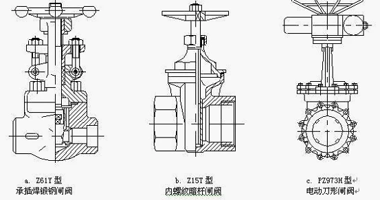
2. Gate valve, slide valve
The opening / closing piece (shutter) is driven by the valve stem and moves up and down along the valve seat (sealing surface).
3. Globe valve (stop valve)
The open-close type (valve) is driven by the valve stem and moves up and down along the axis of the valve seat (sealing surface).
4. Throttle valve
The valve is adjusted by changing the cross-sectional area of the passage through the opening and closing parts (valves).
5. Ball valve
On-off (spherical) valve that rotates around a curve perpendicular to the passage.
6. Butterfly valve
On-off type (butterfly) valve that rotates around a fixed axis.
7. Diaphragm valve
The opening and closing type (diaphragm) is driven by the valve stem, which moves up and down along the axis of the valve stem and separates the action mechanism from the medium.
8. Cock valve (cock)
On-off type (plug) valve that rotates around its axis.
9. Check valve, non-return valve
Opening and closing type (valve flap) uses the force of the medium to automatically prevent the medium from flowing back.
10. Safety valve (safety valve, relief valve)
Open-close type (valve) When the medium pressure in the pipeline or machine equipment exceeds the specified value, it automatically opens and discharges; when it falls below the specified value, it automatically closes and protects the pipeline or machine.
11. Pressure reducing valve
By throttling the opening and closing parts (valves), the medium pressure is reduced, and by the direct effect of the pressure behind the valve, the pressure behind the valve is automatically maintained within a certain range.
12. Steam trap
A valve that automatically drains condensate and prevents steam leakage.
13. Draining Valves
Valves used for blow down of boilers, pressure vessels and other equipment.
14. Low pressure valve
Various valves with nominal pressure PN≤1.6MPa.
15. Middle pressure valve
Various valves with nominal pressure PN≥2.0 ~ PN <10.0MPa.
16. High pressure valve
Various valves with nominal pressure PN≥10.0MPa.
17. Super high pressure valve
Various valves with nominal pressure PN ≥ 100.0MPa.
18. High temperature valve
Used for various valves with medium temperature> 450 ℃.
19. Sub-zero valve
Used for various valves with medium temperature of -40 ℃ ~ -100 ℃.
20. Cryogenic valve
Used for various valves with medium temperature <-100 ℃.
Valve structure terminology
1. Structure length (face-to-face dimension, face-to-centre dimension)
The distance between the inlet and outlet end faces of the valve; or the distance from the inlet end face to the outlet axis.
2. Straight-through valve structure length
(Through way type of valves Face to face dimensions)
The distance between two planes perpendicular to the valve axis at the end of the valve body passage.
3. Angle valve structure length
(Angle type of valves Face to face, end to end, center to face and center to end dimensions)
The distance between a plane perpendicular to the axis at one end of the valve body passage and the axis of the other end of the valve body.
4. Structure form (type of construction)
The main features of various valves in structure and geometry.
5. Straight-through (through way type)
The valve body form in which the inlet and outlet axes coincide or are parallel to each other.
6. Angle type
The valve body with inlet and outlet axes perpendicular to each other.
7. DC type (y-globe type, y- type, diabetes type)
The passage is in a straight line, and the valve stem is in the form of an acute angle with the valve body passage axis.
8. Three way type
The valve body has three passage directions.
9. T-pattern three ways
The path of the stopper (or sphere) is a three-form "T".
10. L-pattern three ways
The path of the stopper (or sphere) has the general formula of "L".
11. Balance type
The use of medium pressure to balance its axial force on the valve stem structure.
12. Lever type
Use the lever to drive the opening and closing parts.
13. Normally open type (normally open type)
When there is no external force, the opening and closing parts are automatically in the open position.
14. Normally closed type
When there is no external force, the opening and closing parts are automatically in the closed position.
15. Insulation type (steam jacket type)
Various valves with steam heating jacket structure.
16. Bellows seal type
Various valves with bellows structure.
17. Full-opening valve
The valve with the same inner diameter of the flow channel in all parts of the valve as the nominal pipe inner diameter.
18. Reduced-opening valve
A valve with a reduced diameter of the flow passage hole in the valve.
19. Reduced-bore valve (reduced-bore valve)
The diameter of the flow passage hole in the valve is reduced, and the flow passage opening of the valve closing member is a non-circular valve.
20. One-way valve (un-directional valve)
Designed as a valve with only one medium flow direction sealed.
21. Bi-directional valve
Designed as a valve with both media flow directions sealed.
22. Double seat two-way valve
(Twin-seat, both seats bi-directional, valve)
The valve has two sealing seats, and the two medium flow directions of each valve seat can be sealed.
23. One-way seat, one-way seat double seat valve
(Twin-seat, one seat un-directional and one seats bi -directional , valve)
The valve with two sealing pairs can keep the sealing state at the same time in the closed position. The valve body in the middle cavity (between the two sealing pairs) has an interface to discharge the medium pressure. Represents the symbol DBB.
24. Upper seat (back seat, back face)
When the valve is fully open, a sealing structure that prevents the medium from leaking from the stuffing box.
25. Pressure seal (pressure seal)
The pressure of the medium is used to realize the automatic sealing structure at the connection between the valve body and the valve cover.
26. Valve stem head size (dimension of valve stem head)
The structural dimensions of the connection parts between the valve stem and the hand wheel, handle or other manipulation machinery.
27. Dimensions of valve stem end (dimension of valve stem end)
The structural size of the connecting part of the valve stem and the opening and closing parts.
28. Connection slot size (dimension of connecting channel)
The structural size of the connection part between the opening and closing parts and the valve stem.
29. Connection form (type of connection)
Various methods used for the connection of valves and pipelines or machinery and equipment (such as flange connection, thread connection, welding connection, etc.). Power plant forged steel control valve sometimes was designed with butt welding type.
Valve parts terminology

1. Valve body
It is directly connected to the pipeline (or machinery and equipment) and forms the part of the medium circulation channel.
2. Valve cover (bonnet, cover, cap, lid)
It is connected with the valve body and forms the main part of the pressure chamber with the valve body (or through other parts, such as diaphragm).
3. Opening and closing (disc)
A general term for a part that is used to intercept or regulate the flow of media, such as the gate plate in a gate valve and the flap in a throttle valve.
4. Disc (disc)
Opening and closing parts in valves such as globe valves, throttle valves, check valves, etc.
5. Valve seat (body seat ring, shoulder seated, bottom seat)
Installed on the valve body, and the opening and closing parts form a seal pair.
6. Sealing face
The opening and closing parts tightly fit the valve seat (valve body) and have two contact surfaces for sealing.
7. Valve stem ( stem,)
The main parts that transmit the opening and closing force to the opening and closing parts.
8. Valve stem nut (yoke bushing, yoke nut)
It forms part of the motion pair with the valve stem thread.
9. Packing box
The valve cover (or valve body) is filled with packing to prevent the medium from leaking from the stem.
10. Stuffing box (stuffing box)
Parts filled with packing to prevent medium leakage from the valve stem.
11. Packing gland ( gland, gland flange, one-piece gland )
Used to compact the packing to reach the sealed part.
12. Packing ( packing, packing rings)
Packed in the stuffing box (or stuffing box) to prevent the filler from leaking at the double stem of the medium.
13. Packing seat (packing seat, packing washer)
Support packing and keep packing sealed parts.
14. Bracket (yoke)
On the valve cover or valve body, it is used to support the stem nut and the transmission mechanism parts.
15. Hit the hand wheel
( Impact hand wheel , hammer blow hand wheel impact hand wheel , hammer blow hand wheel )
Hand wheel structure that uses impact force to reduce valve operating force.