 +86 512 68781993


Harmful phenomena during control valve operation
The first harmful phenomenon to be mentioned is severe noise, which affects the health of employees and the working environment. Noise is a symptom that originates inside the valve and often affects the durability of the equipment or even damages it. The principle of valve noise can be divided into the following: mechanical, aerodynamic and fluid power. Mechanical noise may be caused by vibration, resonance, misalignment of moving parts, or excessive clearances within the valve. Aerodynamic noise occurs because the mechanical energy of the compressible medium flow is converted into sound energy. As the medium decompresses, the released energy accelerates the flow of the fluid—often exceeding the speed of sound—and creates noise. Hydrodynamic noise is generated by fluid flow, including: turbulent flow collisions with valve and pipe walls, cavitation (cavitation) and evaporation (flash).
Cavitation (cavitation)
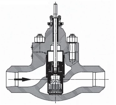
Figure 1. Cage Control Valve
The cavitation always moves downstream, and when the cross-sectional area of the flow channel becomes larger, the flow rate of the medium decreases and the pressure increases. In this case, cavitation occurs, the internal pressure of which is the same as the pressure of the steam in the flow channel, but lower than the pressure of the surrounding medium. The bubbles then collapse inward and disappear. The formation of cavitation, the blocked flow caused by the cavitation, and the subsequent collapse and disappearance of the cavitation downstream is the so-called cavitation phenomenon. When the cavitation collapses, it will make a popping sound, and the noise made by the collapse of countless cavities is like countless broken stones passing through a valve. This noise is so loud that it can even cause hearing damage to people who are exposed to it for a long time. Not only that, but the collapse of the cavitation creates a shock wave that can cause serious damage to the valve.
Flash
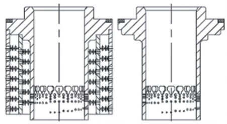
Figure 2 Porous Cage Spool for Control Valve
In addition to collapsing and disappearing, cavitation bubbles can also become larger. The result is that the liquid with the cavities quickly transforms into a vapor containing fine droplets. This is the phenomenon of flash evaporation. The damage caused by flash evaporation is quite different from that caused by cavitation, which can leave parts with looming smooth grooves. The mechanism of this damage is similar to sandblasting. Downstream of the constriction, the fluid contains a large amount of steam and a large number of fine droplets. As the liquid evaporates, its volume increases significantly, so downstream flow rates can reach hundreds of feet per second, and the high velocity droplets can wash away valve components. Damage from flash evaporation usually does not occur as instantaneously as cavitation.
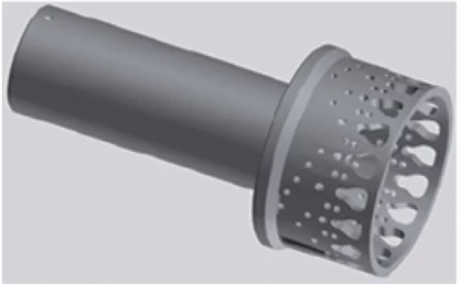
Figure 3 Porous plug for control valve
Solution
As previously mentioned, various harmful phenomena can affect the performance and life of the control valve. This is why our "smart valves" product family offers several targeted solutions. For example, a method to reduce noise is to use a cage structure and set the fitting clearance according to the valve operating conditions. As shown in Figure 1. The most important and efficient way to reduce aerodynamic noise is to use a valve with a control element with a hole, such as a holed plug (Figure 2) or a holed cage (sleeve) (Figure 3). Another method is to reduce the flow rate of the medium at the outlet end. To achieve this, the most common measures are to use perforated cage spools, orifice plates or diffusers, using their choke effect to increase outlet port pressure. If the noise is very severe, it may be necessary to use all of the above measures (Figure 4).
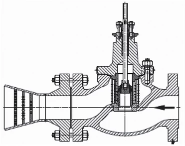
Figure 4 A silent plate at the outlet end of the control valve reduces noise
Improves the durability of valve components
In addition, there is a method that has been proven in use: using thermal spraying, diffusion or plasma nitriding, etc., to coat part or all of the surface of the valve plug and valve seat with a Stellite protective layer, so that the surface of the parts CA. The hardness in the range of 0.1mm reaches 950HV, or the hardness reaches 55HRC by heat treatment. The core design of the anti-cavitation valve is the multi-step cock (Figure 5). The principle of preventing cavitation of the multi-stage cock is that the pressure drop of each stage of the cock is controlled below the critical value. However, the disadvantage of this design is that it is difficult to effectively ensure the effective choke of each stage of the cock when the valve is first opened. For this purpose, we use surface-formed multi-step cocks with holes. Its structure has both an active feature, which provides different resistance depending on the valve opening, and a passive feature, which is the choke effect of the perforated cage spool and orifice plate (Figure 6).
Besides control valves Cowinns consider to improve the durability of valve components for pressure seal gate valve.
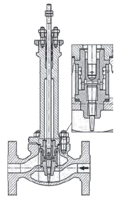
Figure 5. Anti-cavitation valve for small flow
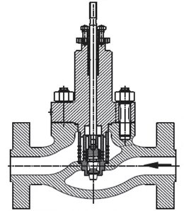
Figure 6. Multi-stage anti-cavitation valve with different choke structures
The occurrence of flash evaporation is determined by various parameters of the fluid, and cannot be completely prevented by design. But the damaging effects of flash evaporation can - and must - be completely eliminated. In addition to improving the durability of valve components by the various methods above, "Smart Valves" can also provide hard coatings on the valve body surface, as well as provide corrosion-resistant gaskets (Figure 7); angle valves (Figure 8); and Valve with Protective Cage (Figure 9).
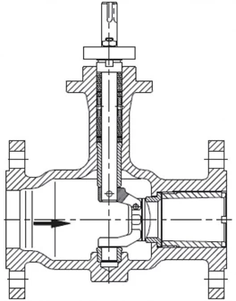
Figure 7. Plug Valve for Flash Service
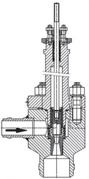
Figure 8. Angle valve for flash service
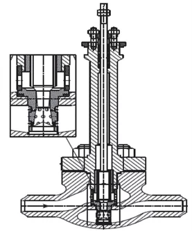
Figure 9. Valve with Guarded Cage