+86 512 68781993


Valve Non-Destructive Testing Technology
Valve Non-Destructive Testing Technology
Overview of Non-Destructive Testing
1.NDT refers to a testing method applied to materials or components without damaging or impacting their future performance or intended use.
2.NDT can detect internal and surface defects in materials or components, measure geometric features and dimensions, and determine the internal composition, structure, physical properties, and conditions of materials or components.
3.NDT is applicable in product design, material selection, manufacturing, final inspection, and in-service inspection (maintenance). It plays an optimal role in balancing quality control and cost reduction. Additionally, NDT helps ensure the safe operation and/or effective use of products.
Types of Non-Destructive Testing Methods
1. NDT encompasses many methods that are already effectively applicable. Based on different physical principles or the objects and purposes of inspection, NDT can be roughly categorized into the following methods:
a) Radiographic Methods:
X-ray and gamma-ray radiographic testing
Radioscopic testing
Computed tomographic testing
Neutron radiographic testing
b) Acoustic Methods
Ultrasonic testing
Acoustic emission testing
Electromagnetic acoustic testing
c) Electromagnetic Methods:
Eddy current testing
Flux leakage testing
d) Surface Methods:
Magnetic particle testing
Liquid penetrant testing
Visual testing
e) Leak Testing Methods:
f) Infrared Methods:
infrared thermographic testing
Note: New NDT methods may be developed and utilized at any time, so other NDT methods may also exist.
2. Conventional NDT methods refer to the currently widely used and well-established NDT methods, which are: Radiographic Testing (RT), Ultrasonic Testing (UT), Eddy Current Testing (ET), Magnetic Particle Testing (MT), and Penetrant Testing (PT).
Safety Precautions
Certain NDT methods may produce or be accompanied by substances such as radioactive radiation, electromagnetic radiation, ultraviolet radiation, toxic materials, flammable or volatile substances, and dust, which can cause varying degrees of harm to the human body. Therefore, when applying NDT, necessary protection and monitoring should be implemented in accordance with relevant regulations or standards based on the types of harmful substances that may be generated. Necessary occupational safety measures should be taken for relevant NDT personnel.
Scope and Limitations of Conventional Non-Destructive Testing Methods
1.Each NDT method has its own scope and limitations, and the probability of detecting defects varies for different methods; it will not be 100% nor completely the same. For example, the results of radiographic testing and ultrasonic testing on the same inspected object may not be entirely consistent.
2.Among conventional NDT methods, radiographic testing and ultrasonic testing are primarily used to detect internal defects of the inspected object; eddy current testing and magnetic particle testing are used to detect surface and near-surface defects; penetrant testing is used solely for detecting surface-opening defects.
3.Radiographic testing is suitable for detecting volumetric defects inside the inspected object, such as porosity, slag inclusions, shrinkage, and looseness; ultrasonic testing is suitable for detecting planar defects inside the inspected object, such as cracks, white spots, layering, and lack of fusion in welds.
4.Radiographic testing is often used for inspecting metal castings and welds, such as BW 900LB gate valve,it’s BW ends were tested by RT, while ultrasonic testing is commonly used for inspecting metal forgings, profiles, and welds. In terms of the ability to detect defects in welds, ultrasonic testing generally outperforms radiographic testing.
Radiographic Testing (RT)
1.Scope of Capability:
a) Capable of detecting defects such as lack of fusion, porosity, and slag inclusions in welds;
b) Capable of detecting defects such as shrinkage, slag inclusions, porosity, looseness, and hot cracks in castings;
c) Can determine the planar projection location and size of detected defects, as well as the types of defects.
Note: The penetrability thickness of radiographic testing is primarily determined by the energy of the radiation. For steel materials, the penetrability thickness of 400 kV X-rays can reach approximately 85 mm, the penetrability thickness of cobalt-60 gamma rays can reach approximately 200 mm, and the penetrability thickness of 9 MeV high-energy X-rays can reach approximately 400 mm.
2.Limitations:
a) It is relatively difficult to detect defects in forgings and profiles;
b) It is relatively difficult to detect small cracks and lack of fusion in welds.
UT
1.Scope of Capability:
a) Capable of detecting defects such as cracks, white spots, delaminations, and large or dense slag inclusions in forgings;
Note 1: Direct transmission techniques can detect internal defects or defects parallel to the surface, with a maximum effective detection depth of about 1 meter for steel materials;
Note 2: Angle beam techniques or surface wave techniques can detect defects that are not parallel to the surface or surface defects.
b) Capable of detecting defects such as cracks, lack of penetration, lack of fusion, slag inclusions, and porosity in welds;
Note: Typically, angle beam techniques are used. When detecting steel welds with 2.5 MHz ultrasonic waves, the maximum effective detection depth is approximately 200 mm.
c) Capable of detecting defects such as cracks, folds, delaminations, and flaky slag inclusions in profiles (including plates, pipes, bars, and other profiles);
Note: Liquid immersion techniques are commonly used, and focused angle beam techniques can also be applied to pipes or bars.
d) Capable of detecting defects such as hot cracks, cold cracks, looseness, slag inclusions, and shrinkage in castings (such as simple-shaped cast steel parts or spheroidal graphite cast iron with smooth surfaces or machined finishes);
e) Can determine the coordinate location and relative size of detected defects, but it is more difficult to identify the type of defects.
2. Limitations:
a) It is relatively difficult to detect defects in coarse-grained materials (such as castings and welds of austenitic steel);
b) It is relatively difficult to detect defects in components with complex shapes or rough surfaces.
ET
1. Scope of Capability:
a) Capable of detecting defects such as cracks, folds, pits, inclusions, and looseness at or near the surface of conductive materials (including ferromagnetic and non-ferromagnetic metals, graphite, etc.);
b) Can determine the coordinate location and relative size of detected defects, but it is difficult to identify the type of defects.
2. Limitations:
a) Not suitable for non-conductive materials;
b) Cannot detect internal defects located at a considerable depth within conductive materials;
c) Relatively difficult to detect defects at the surface or near the surface of components with complex shapes.
MT
1. Scope of Capability:
a) Capable of detecting defects such as cracks, folds, laminations, inclusions, and porosity at or near the surface of ferromagnetic materials (including various components like forgings, castings, welds, and profiles);
b) Can determine the location, size, and shape of detected defects on the surface of the inspected object, but it is difficult to ascertain the depth of the defects.
2. Limitations:
a) Not suitable for non-ferromagnetic materials, such as austenitic steel, copper, aluminum, and other materials;
b) Cannot detect internal defects located at a considerable depth within ferromagnetic materials.
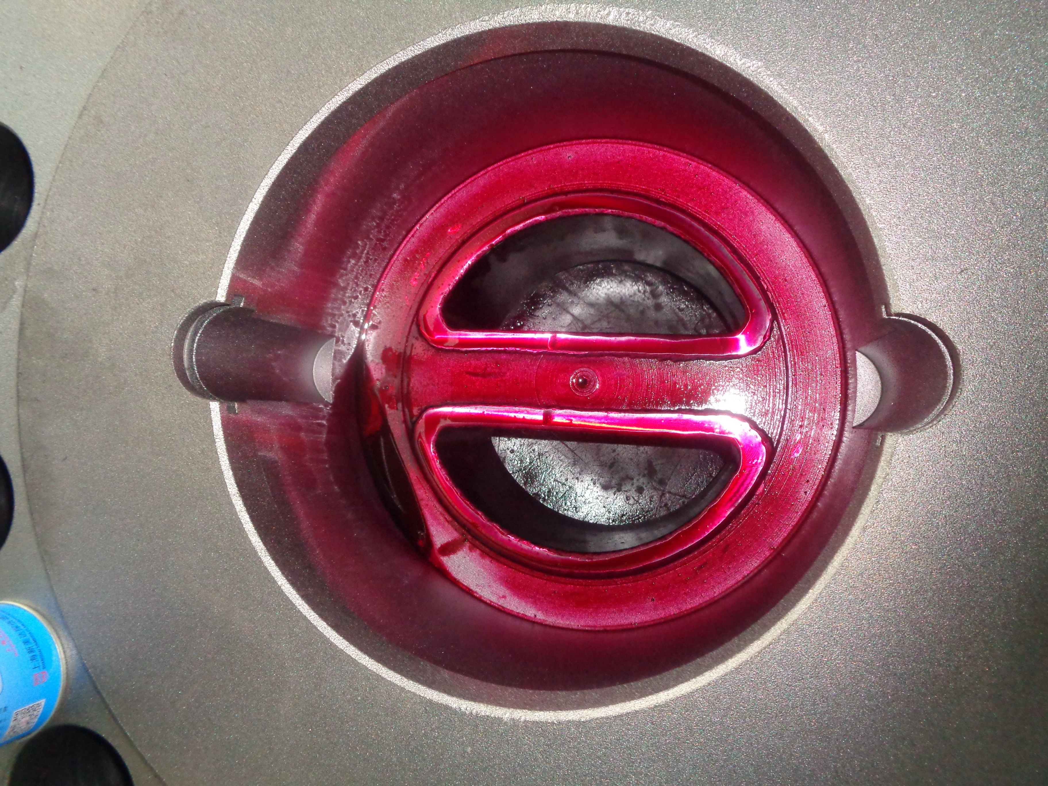
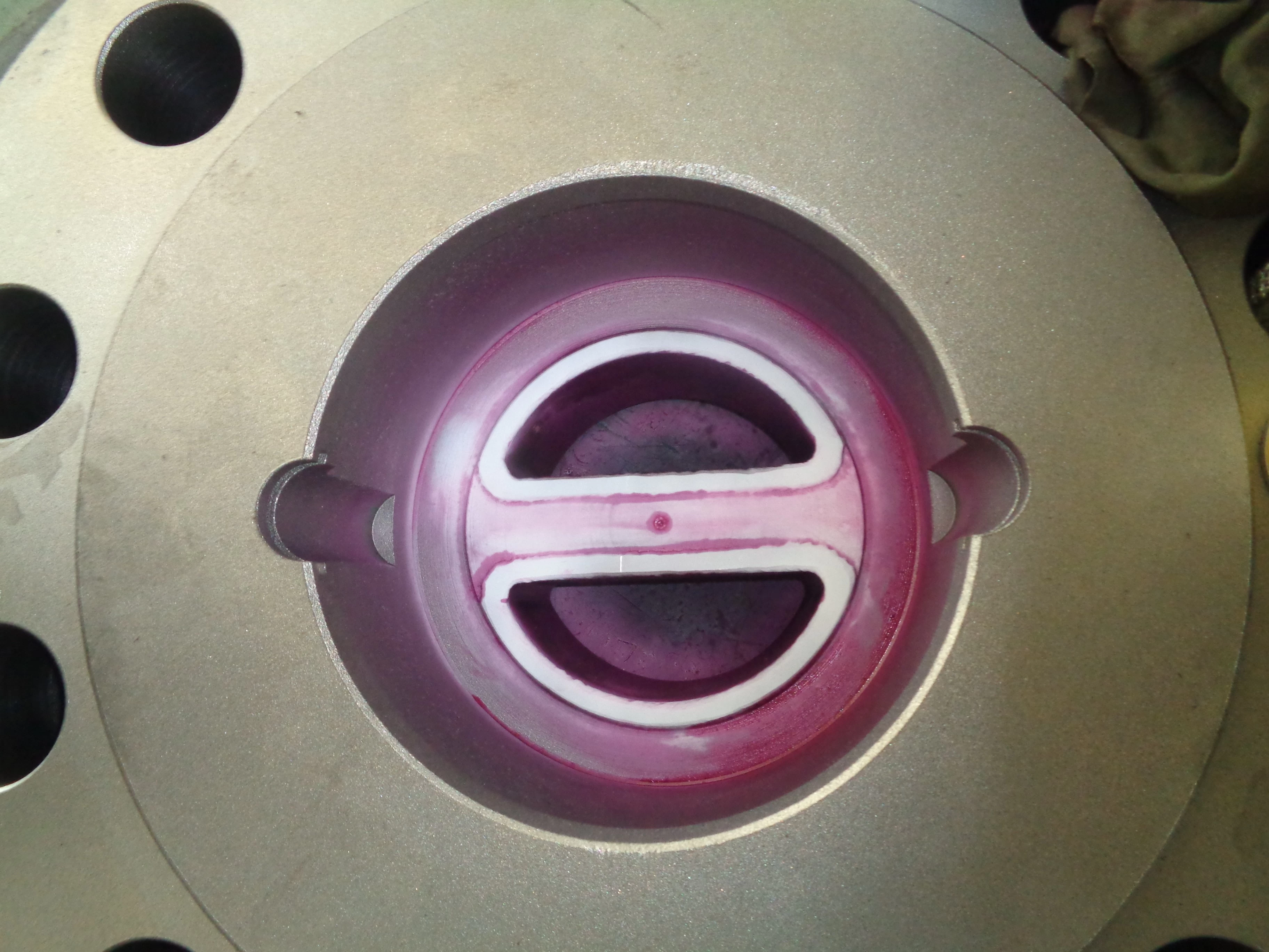
PT
1. Scope of Capability:
a) Capable of detecting open surface defects such as cracks, folds, looseness, and pinholes in metallic materials and dense non-metallic materials;
b) Can determine the location, size, and shape of detected defects on the surface of the inspected object, but it is difficult to ascertain the depth of the defects.
2. Limitations:
a) Not suitable for loose, porous materials;
b) Cannot detect defects that are internal and/or near the surface of the material when the surface is not open.