Boiler Terminology Explanation (Part 19)
Boiler Terminology Explanation (Part 19)
181.Variable Pressure Operation: Variable pressure operation refers to keeping the turbine inlet regulating valve fully open or partially open, and adjusting the boiler outlet steam pressure (while keeping the temperature constant) to meet the electricity grid load requirements. This is also known as sliding pressure operation. Types of variable pressure operation: According to how the turbine inlet regulating valve opens during load changes, variable pressure operation can be classified into pure variable pressure operation, throttling variable pressure operation, and composite variable pressure operation.
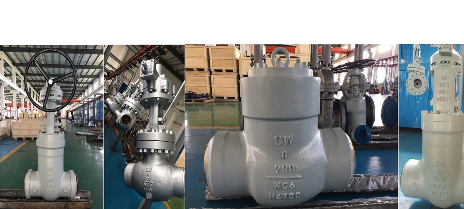
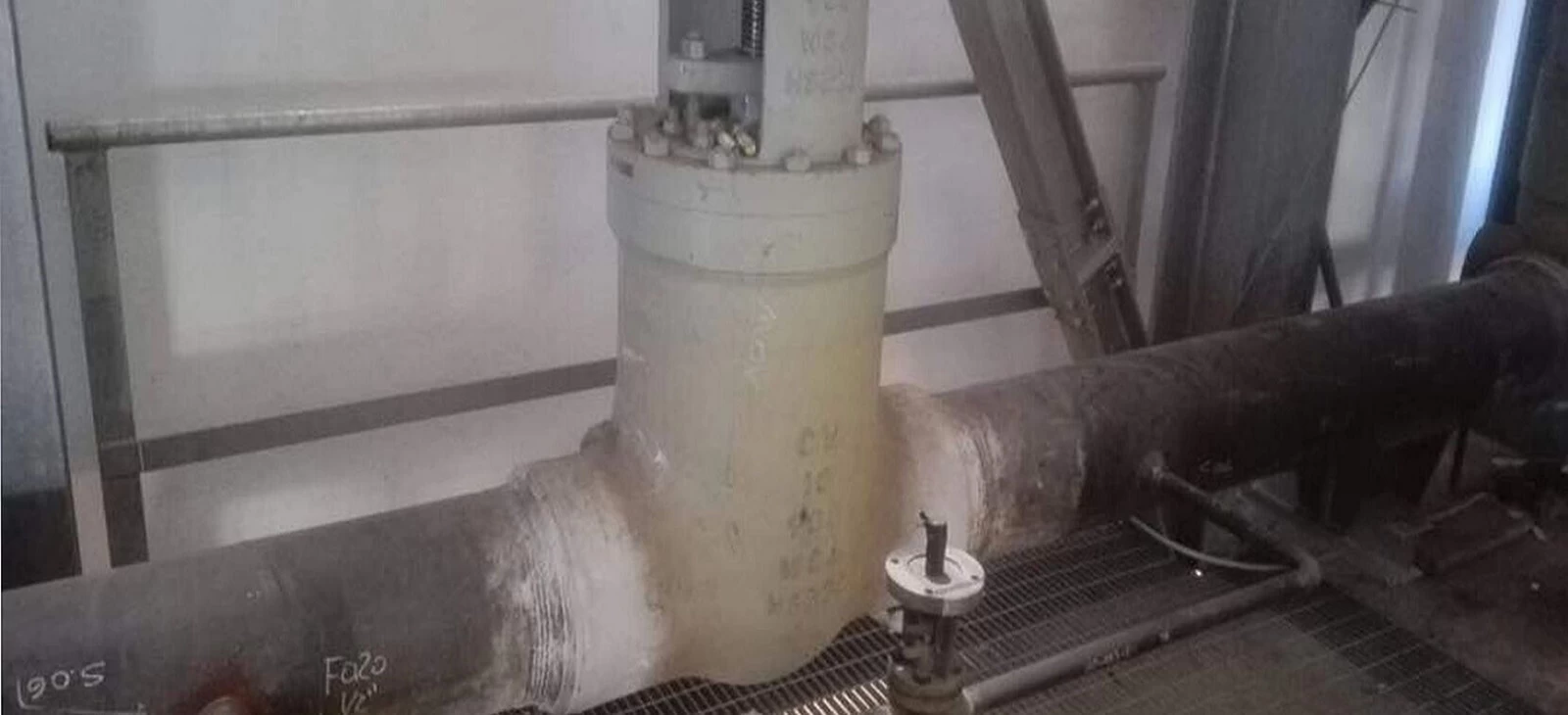
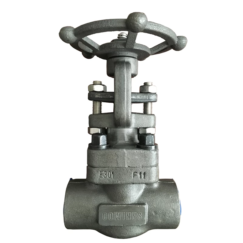
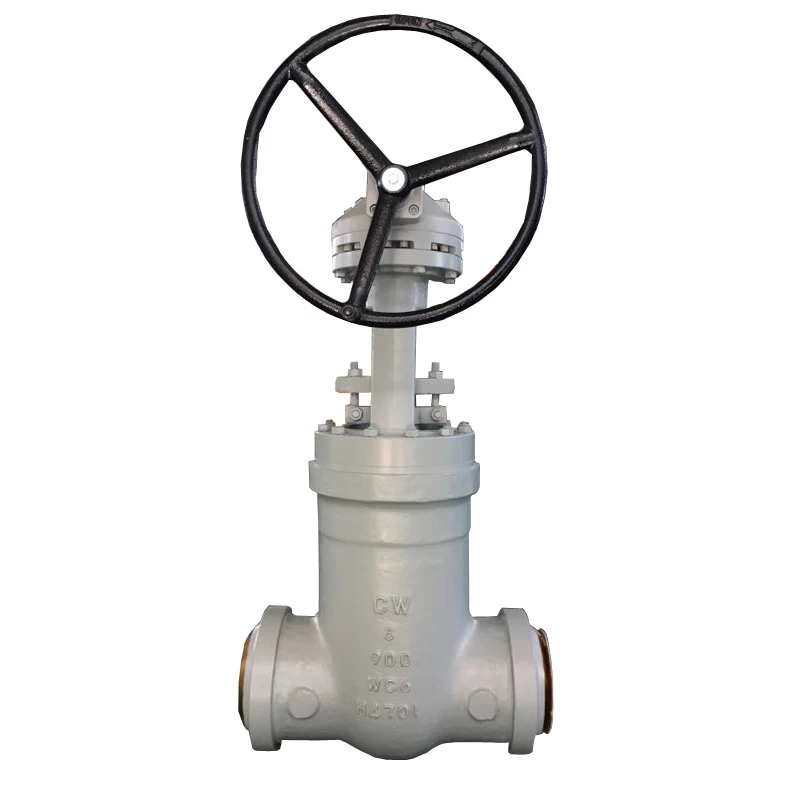
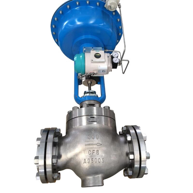
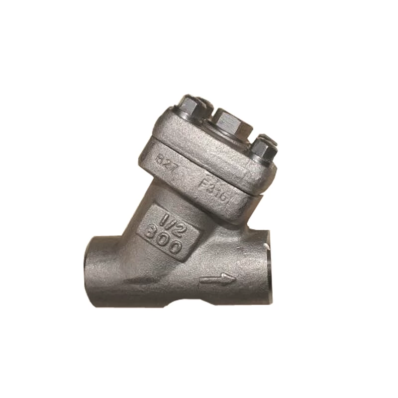
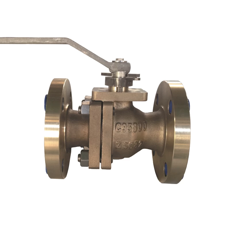
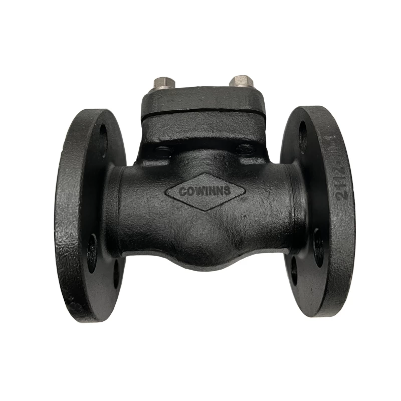
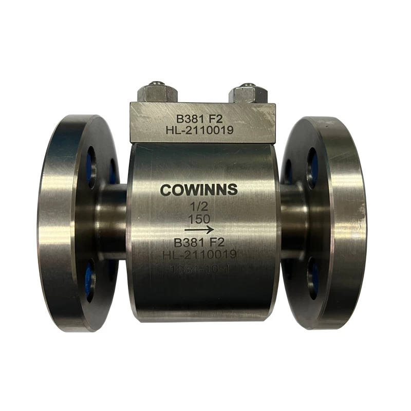
Pure Variable Pressure Operation: In this mode, the turbine inlet regulating valve is fully open across the entire load variation range, and the main steam pressure is adjusted by the boiler to match the load changes. However, this mode involves significant delay, poor load adaptability, and cannot meet frequency regulation requirements. Furthermore, at low loads, with the valve fully open and low steam pressure, the unit’s cycle efficiency significantly decreases. Additionally, during such operations, components like the Inconel 625 dual plate wafer check valve are crucial for handling high-temperature and high-pressure steam to ensure optimal performance and reliability under these varying conditions.
Throttling Variable Pressure Operation: Under normal operating conditions, the turbine inlet regulating valve is not fully open but throttled. As the load increases, the valve is fully opened, utilizing the boiler’s energy storage to achieve quick load increase. Afterward, as the boiler steam pressure rises, the valve returns to its original position. This operation mode solves the delay issue in pure variable pressure operation. However, throttling losses during normal operation may reduce the unit’s economic efficiency. In such cases, using advanced components such as the Inconel 625 dual plate wafer check valve helps maintain system stability by effectively managing steam flow and pressure.
Composite Variable Pressure Operation: This operation mode combines variable and constant pressure operations. For turbines with nozzle regulation, there are three combinations: (1) Low load variable pressure operation, high load constant pressure operation; (2) High load variable pressure operation, low load constant pressure operation; (3) High and low load constant pressure operation, with variable pressure operation at intermediate loads.
182.Coordinated Control System of Boiler-Turbine-Generator Unit (CCS): When a boiler and turbine generator unit form a combined unit, the coordinated control system automatically adjusts the boiler and turbine generator to adapt to electricity grid load changes while maintaining the unit’s safe and stable operation. This system, also known as integrated boiler-turbine control, ensures that when the load requirement changes, the turbine’s regulating valve opening and the boiler’s combustion rate (and other parameters) are simultaneously adjusted. This minimizes the dynamic deviation of the turbine’s inlet steam pressure and provides a faster power response.
183.Boiler Following Mode: This control method adjusts the turbine’s power while adjusting the boiler steam pressure. When the grid load changes, the turbine’s automatic control system adjusts the regulating valve to change the turbine generator's output power. This causes the steam pressure at the turbine’s inlet to change, which prompts the boiler’s automatic control system to adjust the boiler’s combustion rate (and other parameters like feedwater flow, spray flow, etc.) to maintain the turbine’s steam pressure at the set value. The characteristic of this control mode is a fast initial power response when the load changes, but with large dynamic deviations in the turbine’s steam pressure.
184.Turbine Following Mode: This control method adjusts the boiler’s power while the turbine adjusts the steam pressure. When the load changes, the boiler’s automatic control system adjusts the combustion rate (and other parameters) to change the steam pressure. Once the steam pressure changes, the turbine’s automatic control system adjusts the regulating valve opening to maintain the turbine’s steam pressure at the set value and simultaneously adjusts the turbine generator’s output power. The characteristic of this control mode is a smaller dynamic deviation in steam pressure, but slower power response.
185.Automatic Load Reduction (Runback, RB): When there is a fault in part of the auxiliary equipment of the boiler or turbine, the load command automatically decreases to an appropriate level at a preset rate, allowing the unit to continue operation at a lower load.
186.Fast Cutback (FCB): In the event of a fault in the electrical or turbine system (e.g., generator and grid disconnection), this operation reduces the load to the minimum level that the boiler can maintain stable operation, so that after the fault is cleared, the load can be increased quickly. After issuing the FCB command, the coordinated control system switches to manual control, while the turbine bypass control system and boiler burner management system also coordinate to ensure stability.
187.Distributed Control System (DCS): Based on microprocessors and microcomputers, a distributed control system integrates computer technology, data communication technology, CRT screen display technology, and automatic control technology. It is used for centralized management and decentralized control of the production process. The DCS consists of control stations distributed throughout the production process, each using a microprocessor to control a portion of the process, and linked together via a data communication system with the central control room, hence it is also known as Total Distributed Control System (TDCS).
188.Data Acquisition System (DAS): This system collects and processes operational parameters and statuses of the unit, and is used for display, alarm, and report generation.
189.Auxiliary Equipment Sequence Control System (SCS): A control system that manages the start/stop control and interlocking protection of the unit’s main auxiliary equipment.
190.Boiler Hydrostatic Test: To check the boiler’s thermal tightness and strength, an overall hydrostatic test is conducted after the heating surfaces and pipelines are installed. This test includes all steam-water pipelines and valves from the feedwater inlet to the main steam valve or turbine inlet valve. If a secondary reheat boiler is present, the secondary steam system also undergoes a hydrostatic test. The test pressure is according to the manufacturer’s specifications. Deionized water is used for the test, and to prevent equipment corrosion, a certain amount of ammonia or amine is added during the water intake process. Since a large amount of water is required, the water volume for the test is calculated, and temporary water storage containers are prepared. If any leakage occurs during the test, the water must be drained before repairs can be made. Therefore, a preliminary air pressure test is performed before the hydrostatic test. Since air leaks at a much higher rate than water, the air pressure is set between 0.3 and 0.5 MPa to ensure no leaks, after which the hydrostatic test is carried out.
 +86 512 68781993