 +86 512 68781993


Bypass control system
1. Bypass composition
This bypass system is composed of control, valve and pneumatic actuator. The control is implemented by DCS, and the control strategy and principle are for reference. The valve is a pneumatic actuator (similar to a hydraulic bypass). The bypass system valves are configured as high-side temperature and pressure reducing valve (BP), high-side water spray control valve (BPE), high-side water spray isolation valve (BD) and low side temperature and pressure reducing valve (LBP), low side Spray control valve (LBPE), low side spray isolation valve (LBD) and three-stage spray control valve.
2. Equipment performance requirements
1. Improve the starting performance of the unit
When the unit is started with a high-pressure cylinder or an intermediate-pressure cylinder under various working conditions (cold, warm, hot, and extremely hot), the bypass system is used to control the boiler steam temperature to make it relatively quickly to the metal temperature of the turbine cylinder Matching, thereby shortening the start-up time and reducing steam emission to the air and reducing the cycle life loss of the steam turbine, realizing the best start-up of the unit.
2, unit normal operation, the bypass device as a main high-pressure steam pressure overpressure protection safety device, once the main steam vapor pressure exceeds the set value of the high-pressure bypass means, a high-pressure bypass valve should open quickly, and in accordance with the main steam unit The pressure is adjusted until it returns to the normal value; the low-pressure bypass device adjusts the reheating steam pressure according to the unit load (regulation stage pressure). When the reheating steam pressure exceeds the corresponding steam pressure of the load, the low-pressure bypass opens to adjust and controls the reheated steam pressure.
3, the bypass system of the device should withstand constant pressure and sliding pressure unit two operation modes, and the control unit with a real current load regulation.
4. When the power grid or the unit fault trips and load rejection, the bypass system device should act quickly (high side quickly open, low side quickly open at the same time) to achieve the function of maintaining the minimum load operation of the boiler, so that the unit can reconnect to the grid at any time and resume normal operation .
5. During start-up and load rejection, the bypass system device should be able to protect the reheater arranged in the higher smoke temperature area to prevent burnout.
6. The bypass system device should be able to recover working fluid and reduce noise. The equipment performance of the bypass system should satisfy that the unit can automatically or manually (remote control operation) under various working conditions (including start-up, normal operation, load shedding), normal action and rapid action (high side fast open 3 seconds, high Normally adjust for 13 seconds at low side, fast off at low side for 3 seconds, and normal adjust at low side for 13 seconds).
7. The bypass system device should have the following two protection functions
(1) The safety protection function of the high pressure bypass to the new steam piping system
When one of the following situations occurs during the operation of the unit, the high-pressure bypass should be able to automatically and quickly open within 3 seconds
The pressure of the new steam exceeds the safety protection setting value (slightly lower than the safety valve take-off value). When the pressure is restored to the set timing value and below, the high pressure bypass closed automatically.
The steam turbine trips and the automatic main steam valve closes;
The generator oil switch trips;
When the generator dumps load.
(2) on the low pressure bypass security features CONDENSER: when the unit of the following conditions in the starting or running time occurred, low side should quickly turn off automatically within 3 seconds.
The vacuum of the condenser is lower than the set value;
The temperature of the condenser is higher than the set value;
Low side outlet pressure or temperature is higher than the set value;
The pressure of the low side desuperheating water is lower than the set value.
The liquid level of the condenser is higher than the set value.
8. The control system should reliably ensure that the bypass valve action meets the following requirements:
(1) When the opening of the high-pressure bypass valve is below 95%;
When the pressure of new steam rises, the valve should gradually open accordingly;
When the pressure of new steam drops, the valve should be closed gradually;
(2) When the opening of the high-pressure bypass valve is above 95%;
When the pressure of new steam rises, the valve should hardly move
The new steam pressure drops, the valve should be operated in the closing direction along until the pressure reaches the set value of the stop;
9. The bypass device should have the following interlock protection means
(1) When the spray water control valve or bypass isolation valve open high, the high temperature valve should be in hypoparathyroidism not hit the open state.
(2) When the high side temperature and pressure reducing valve is opened, the high side water spray isolation valve opens in a chain.
(3) When the high side temperature reducing and pressure reducing valve is closed, the high side spray water regulating valve and the high side spray water isolation valve should be closed at the same time , and the temperature control system should be automatically blocked.
(4) When the low side water spray regulating valve cannot be opened, the low side temperature and pressure reducing valve should not be opened.
(5) When the low-pressure bypass valve is opened, the low-side spray water isolation valve should be opened interlockingly.
(6) When the low side temperature reducing and pressure reducing valve is closed, the low bypass water spray regulating valve should be closed at the same time.
(7) when the low pressure bypass valve to close quickly, the valves shut off the high plant conditions according to a manual or automatic (remote control) closed.
10. For the bypass valve system, when the control power supply in action is suddenly cut off, the valves should be automatically closed at this time .
11. The control system should have an interface with DEH.
3. Bypass operation mode
The bypass has three operating modes, starting mode, sliding pressure mode and constant pressure mode
1. Starting method
The start mode is called the valve position mode, which is the bypass operation mode from the ignition of the boiler to the impulse of the steam turbine. The start mode is divided into the high pressure cylinder start mode and the intermediate pressure cylinder start mode. Both the high pressure cylinder start mode and the intermediate pressure cylinder start mode are controlled by the minimum opening at the beginning. At this time, the main steam pressure and the heat reheat pressure are less than the minimum pressure setting. The high bypass valve BP and low bypass valve LBP cannot be opened automatically, but are forced to open through a minimum opening. The BP and LBP valves maintain the minimum opening before the main steam pressure and the heat reheat pressure reach the corresponding minimum pressure settings. No change, the steam passes through the high-pressure bypass, reheater and low-pressure bypass heating piping system. When the main steam pressure and heat reheat pressure rise to the minimum pressure setting, the control loop maintains the minimum pressure setting, so that BP and LBP are gradually opened. , And finally reach the set maximum opening, that is, the maximum opening control. At this time, the high side maintains the maximum opening, and the main steam pressure gradually increases according to the boost rate set by the given value generator. The setpoint generator also has the function of limiting the rate of rise of main steam pressure. The low-pressure bypass situation is similar to the high-pressure bypass.
2. Constant pressure method
In the high-pressure cylinder starting mode, when the main steam pressure rises to the set pressure value, it automatically enters the constant pressure operation mode, and the bypass system valve keeps this pressure unchanged and waits for the unit to flush. When various conditions are met and the unit is ready to flush, the operator presses the "Rush" button on the CRT, and the high bypass valve BP begins to close, causing the main steam pressure to rise further until the high bypass valve is completely closed. Pressure is the impulse pressure, high side
After closing, and the reheat pressure is less than ()kg/cm2, the low pressure bypass valve LBP begins to close gradually. When all the bypass valves are fully closed and the heat reheat pressure is less than ()kg/cm2, the DEH system selects the "bypass cut" mode, and the steam turbine can start to rotate. At this point, the start mode of the high-pressure cylinder ends, and the bypass system exits. All bypass valves remain closed, but the bypass system is still in hot standby state.
When the medium pressure cylinder is started, the high side valve keeps its maximum opening, the main steam pressure rises according to the pressure rise rate set by the given value generator, and the heat reheat pressure rises accordingly. When the main steam pressure rises to () kg/cm2, the bypass system will automatically switch to a constant pressure operation mode. At this time, the pressure setting value is kept constant to ensure the main steam pressure when the steam turbine starts and realize constant pressure start. When the main steam pressure and main steam temperature required by the impulse conditions are met, the turbine starts to impulse and increase its speed. At this time, the steam consumption of the turbine increases and the high bypass valve is correspondingly closed to maintain the front pressure at () kg/cm2. After the turbine is increased to 3000rpm and connected to the grid with initial load, the bypass is still in constant pressure operation, and the high bypass valve plays a role of pressure regulation. When the main steam pressure is greater than the set point, the high bypass valve opens, and when the main steam pressure is less than the set point, the high bypass valve closes. During this process, the low side valve maintains the minimum pressure setting.
As the boiler combustion rate increases, the load of the steam turbine gradually rises. When the load of the steam turbine rises to () % of the rated load , the high bypass valve should be closed gradually. Finally, when the high side door is completely closed, the bypass system automatically switches to sliding pressure operation mode.
Three, sliding pressure method
In the sliding pressure operation mode, the set value of main steam pressure and heat reheat pressure automatically track the actual value of main steam pressure and heat reheat pressure, and as long as the pressure rise rate of fresh steam pressure is less than the set pressure rise rate limit value, The pressure setting value is always slightly greater than the actual pressure value, that is, P setting value = P actual + ΔP, so as to ensure that the bypass valve is closed.
When the turbine load> () %, and the high and low pressure bypass valves are completely closed, the operator can select the bypass continue on or bypass cut operation mode on the DEH operation panel. If the bypass system is cut off, the bypass control system exits operation and is in a hot standby state. If the bypass system continues to work, if the boiler outlet pressure is disturbed during operation, and the pressure rise rate ΔP/Δt is greater than the limit value, the high bypass valve will open instantly. After the disturbance passes, the fixed value is greater than the actual value, and the high bypass valve closes again. Once the high bypass valve is opened, the sliding pressure mode is immediately converted to the constant pressure mode, and the pressure constant value is the pressure fluctuation value at the moment of the transition plus the pressure deviation ΔP.
The above parameter data sets actually need to be set and can be modified online.
Four, bypass control mode
Bypass control should provide users with two control methods for users to choose and use according to the actual situation on site. These two control methods are automatic-remote control manual respectively. The priority of the latter is higher than the former, and the two methods track each other without disturbance when switching. In any control mode, the bypass control system has interlocking and protection functions between valves.
1. The DCS manufacturer should make at least two pictures for the operator to operate and monitor the bypass
(1) Bypass thermal system diagram, with color to indicate the on-off status of each valve, and the degree of separation and the pressure and temperature parameters before and after the valve are displayed next to the valve .
(2) The control panel of the bypass valve:
?Hand \Auto switch and display button
On and off buttons
Valve position opening indication and its degree of separation
Pressure and temperature parameters before and after the valve, regulating stage pressure, condenser vacuum, etc.
Bypass input and removal
Grid-connected and grid-connected steam turbine
Medium pressure cylinder start
Start, constant pressure, sliding pressure
L Minimum opening, minimum pressure, maximum opening, low side flow limit under start and automatic state
Power failure alarm
Air source failure alarm
?Remove/ restore condenser protection
The operator can use the cursor (or directly use the keyboard) to monitor and control the entire bypass through the relevant buttons.
2. Remote control hand exercise
The operator uses the cursor to switch the bypass control state to manual through the relevant buttons, and then uses the cursor to open and close the switch buttons of each valve .
3. Automatic control
Under the premise that the valve servo system is normal, press "Auto" to switch to automatic control mode. In this mode, the control can be closed-loop control of the high and low bypass valve front pressure and the high and low bypass valve rear temperature, pressure and temperature target values set by the operator on the operator station CRT. At this time, the valve position increase and decrease buttons are invalid.
The bypass is in the automatic control mode, pressing the "Start" button, the control will pass on the CRT screen based on the current status and DEH unit operation mode, the system automatically selects the bypass mode of operation, i.e. starting the high pressure cylinder mode, the Cylinder start mode, constant pressure mode or sliding pressure mode. The bypass control automatically gives the set points of pressure and temperature according to the startup curve, controls each bypass valve, and monitors the main steam pressure, the heat reheat pressure, the high-side temperature, the low-side temperature and various protection conditions. Established to continuously protect equipment safety.
Five, the working principle of bypass control
This bypass control system is composed of seven control circuits, namely the high-pressure bypass pressure control loop, the high-pressure bypass temperature control loop, the high-side spray isolation valve control loop, the low-pressure bypass control loop, the low-pressure bypass temperature control loop, Low side spray water isolation valve and three-stage temperature reduction spray water control loop.
1. High pressure control loop
Operation mode:
When the bypass system is in the start mode, because the main steam pressure is less than the minimum pressure set value output by the set value generator, the input of the DCS regulator is negative, and the output of the DCS regulator is the minimum valve position Ymin . When the main steam pressure rises to the minimum pressure set value Pmin output by the set value generator and continues to increase, the valve position set value Ys output by the DCS regulator gradually increases on the basis of the original set minimum opening Ymin . Ys is compared with the maximum opening of the high bypass valve Ymax , the difference is sent to the set value generator, Ys< Ymax , the set value generator input value is negative, and the set value generator output is Pmin ; Ys> Ymax , The input of the setpoint generator is positive, and the output of the setpoint generator starts to rise from Pmin , so as the main steam pressure rises, the setpoint of the main steam pressure also increases.
When the main steam pressure rises to the impulse pressure, the logic circuit makes the bypass system switch to constant pressure operation, and the main steam pressure is maintained at the value at the moment of switching, that is, impulse pressure. As the steam turbine impulses increases, the steam consumption increases. The high bypass valve is gradually closed. When the high and low bypass valves are completely closed, the bypass system turns to sliding pressure operation mode. Main steam pressure setting value = main steam pressure + ΔP.
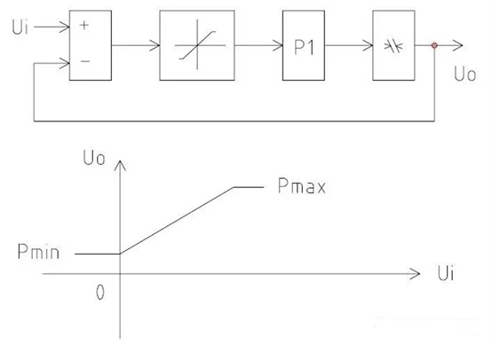
Setpoint generator:
As shown in the figure below, the setpoint generator is a feedback integrator with output limitation. The integrator generates a ramp signal with a certain slope through internal feedback. The given value output has the maximum limit value Pmax and the minimum limit Pmin . The maximum setting value Pmax is the maximum pressure value during normal operation, which is lower than the pressure setting value of the safety valve, and the minimum pressure setting value is set at the minimum pressure control value. When the rate of change of Ui representing the main steam pressure signal is less than the set pressure gradient ΔP/Δt, the output U0 will follow the change of Ui without delay . Once Ui change rate [Delta] Ui when / Δt is greater than ΔP / Δt, for a given value of the generator output U0, will only follow the pressure gradient value ΔP / Δt internally set. Therefore, the set point generator also has the function of limiting the rate of rise of main steam pressure.
Valve position control loop:
The valve position command signal output by the bypass control system after calculation is compared with the actual valve opening value, and the difference is output to the actuator positioner as a 4-20mA signal, and the valve is driven by the actuator to open the valve to the specified opening degree.
2. High pressure bypass temperature control loop
When the bypass system is running, the temperature control circuit sprays water to cool the steam through the water injection valve to the steam expansion chamber of the high bypass valve to keep the temperature after the high bypass valve at the set value. After the high bypass valve, the actual temperature TBP is compared with the temperature setting value to obtain the temperature control deviation, which is sent to the bypass temperature control regulator on the DCS. The output of the regulator is used as a part of the set value of the high bypass water injection valve position. Sent into the valve position control loop.
In order to improve the temperature control characteristics, especially when the steam flow rate is large, the over-modulation of the water injection volume is reduced and the steam flow rate is too small, and the stability of the water injection volume is enhanced. The PD link is used to compensate the time delay of the temperature measuring element, and the controller's time delay is dynamically changed. Amplify the signal to match the steam flow rate.
The steam flow rate is calculated by the function of the main steam pressure and the flow area obtained by the function conversion of the high bypass valve opening. The steam flow signal and the output signal of the regulator are calculated to obtain the valve position fixed value signal of the water spray valve. The proportional relationship between the steam flow and the output signal of the DCS regulator is automatically matched by the operating conditions.
At cold start, the temperature after the high bypass valve is lower than the given temperature, and the DCS regulator outputs force O. Therefore, even if a certain steam flow passes through, the high bypass water injection valve remains closed.
In order to make the water spray valve have a certain opening when the YBP value of the high side valve opening is small, a fixed command of 5% is added to the given value.
3. High side spray water isolation valve control loop
The high-pressure bypass water spray first passes through the high-side spray water isolation valve BD. The function of BD is: one is to act as an isolation valve when the bypass valve is closed; the other is to reduce the feed water pressure. When the BD valve is fully opened, the pressure ratio before and after the BD valve is approximately 0.8 times. The BD valve is two-position control and is interlocked with the high bypass valve BP via a logic circuit. When YBP>2%, the BD valve is fully opened, when YBP≤2%, the BD valve is fully closed, and the opening and closing of BD are indicated on the CRT and the manual operation panel. When the BD valve is not in the fully open or fully closed position, the BD valve open and close indicator lights will flash.
4. Low pressure bypass pressure control loop
The pressure control characteristics of the low pressure bypass are shown in the figure below. In the startup phase, it is the startup mode. At this time, the minimum opening of the low side valve is Ymin , and the pressure setting is the minimum pressure setting Pmin . When the turbine is running, the low-pressure bypass control circuit maintains this minimum pressure. When the load is above %, the outlet pressure of the reheater is proportional to the load. In this stage, the low-pressure part of the steam turbine operates in sliding pressure mode. The pressure setting of the low pressure bypass is the reheater outlet pressure plus a fixed deviation ΔP to ensure that the low bypass valve LBP is closed. The given value of the pressure at the outlet of the reheater is obtained by multiplying the pressure of the high-pressure cylinder of the steam turbine by a coefficient, which is:
K=Heat reheat pressure under rated load/regulating stage pressure under rated load
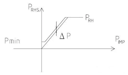
The maximum pressure setting value Pmax in the figure is the maximum pressure setting value of the low side, which should be less than the operating pressure of the reheater safety door. The minimum pressure setting value Pmin is generally set to the minimum control value of the low side pressure.
The difference between the low bypass pressure set value and the reheater outlet pressure is sent to the regulator on the DCS for processing, and the regulator output is the low bypass valve set value Ys. The working principle of the valve position circuit of the low side valve is the same as that of the high side valve.
In order to prevent the condenser from overloading during bypass operation, the steam flow of the low-pressure bypass must be restricted. Here , the pressure after the low bypass valve is restricted to achieve this goal. The pressure PLBPO after the low bypass valve is compared with the pressure limit value PLBPS representing the maximum steam flow. When PLBPO>PLBPS, after low selection, this signal is sent to the regulator to make the low bypass valve LBP move in the closing direction. And display alarm information on CRT.
5. Low-pressure bypass temperature control loop
The low-pressure bypass temperature control loop is the follow-up system of the low-pressure bypass pressure control loop. It can be seen from the block diagram of the regulating system that the opening YLBP of the low-pressure bypass valve is converted into the corresponding flow area and the reheater outlet pressure. After multiplying, get the steam flow through the low side valve. Then it is converted into the set value of the low bypass valve by the function and sent to the valve position control loop of LBPE.
In order to have sufficient spray water under small flow conditions, the minimum opening of the low side spray water regulating valve is 20%.
Six, low side spray water isolation valve control loop
The low pressure bypass water spray first passes through the low side spray water isolation valve LBD. The function of the LBD is to act as an isolation valve when the bypass valve is closed. The LBD valve is two-position control and is interlocked with the low bypass valve LBP via a logic circuit. When YLBP>2%, the LBD valve is fully open; when YLBP≤2%, the LBD valve is fully closed. The opening and closing of the LBD are indicated on the CRT and the manual operation panel. When the LBD valve is not in the fully open or fully closed position, the LBD valve open and close indicator lights will flash.
Seven and three-stage temperature-reducing spray valve control loop
The three-stage water spray regulating valve is also a follow-up system of the low side pressure control loop. As long as the low side temperature reducing valve LBP is opened, it will open. After the low side LBP valve is closed, it will delay for about seconds (parameters can be adjusted online )shut down.
6. Protection and interlocking of bypass control
In addition to the normal adjustment of the bypass system, the bypass control system also has the protection function of the main engine and auxiliary equipment.
1. In order to protect the condenser, the low side system sets five fast shut-off signals:
Low condenser vacuum
High condenser temperature
Condenser liquid level is high
Low side spray water pressure is low
High temperature after low side valve
2. When the following signals appear, the high side valve opens quickly
Turbine tripping
The main steam pressure is too high
3. When the following signals appear, the high side valve closes quickly.
The temperature is too high after high bypass valve
Low side valve failure
? 110% over speed of steam turbine
High side spray water pressure is low
4. When the following signals appear, the low side valve opens quickly:
110% overspeed of steam turbine
Open the high side quickly
Heat and reheat pressure is too high
5. When the bypass control system needs to be opened as soon as possible and the signal to be closed as soon as possible appears at the same time, the logic design is that off has priority over on:
6, the high pressure bypass valve open, closed and open water bypass valve and the high side of the high-water isolation valve, closes the communication lock.
7. The opening and closing of the low pressure bypass valve is interlocked with the opening and closing of the low side spray valve.
8. The opening and closing of the three-stage cooling water spray valve are interlocked with the opening and closing of the low pressure bypass valve.
9. When DEH selects "bypass removal" mode, close the bypass system. That is, when the valve position Y is less than or equal to 2%, the quick- open and quick-close solenoid valves of the valve should all cut off the power to make the valve in a forced closed state.
Seven, bypass control and DEH interface
1. DEH bypass
① Steam turbine hanging brake
② Turbine trip
③ Fully open the medium voltage regulating door
④ Turbine load>%
⑤ 110% over speed of steam turbine
⑥ Heat reheating pressure
⑦ Medium pressure cylinder start
⑧ Cut off the bypass
2. Bypass DEH
① Input of bypass system
② Removal of bypass system
Note: The bypass control is implemented by DCS, so there is no interface problem with DCS.
For power plant system cowinns supplied high pressure control valve to China mainland end users. We will practice more and more similar projects in the future base on good cooperation with end users.