+86 512 68781993


Common faults and maintenance methods of electric actuators
1). Indicator failure
1. Failure phenomenon:
After powering on the electric actuator, it is found that the power indicator is off, the servo board has no feedback, and the signal does not act.
Fault judgment and maintenance process:
Because the power indicator is not bright, first check whether the fuse is open. After checking that the fuse is intact, the comprehensive fault phenomenon can be inferred that the fault may occur in the power supply part of the servo amplifier board. Then check the power indicator and use a multimeter to detect the indicator. Open the circuit, replace the indicator and troubleshoot.
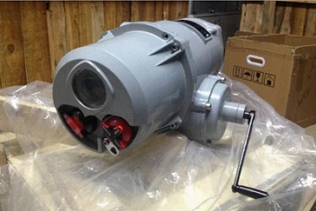
Conclusion: The open circuit of the power indicator will cause the whole servo amplifier board not to work. We should pay more attention on power plant Rotork electrical actuator control valve, this type valve always apply for high pressure pipeline.
2. Failure phenomenon: (found during debugging)
After the actuator of the electric actuator is energized, the signal can be turned on, but not turned off.
Fault judgment and maintenance process: first carefully check the feedback circuit, confirm that the feedback signal is not faulty, the indicator light is on when the signal is turned on, indicating that the switch is on, and the indicator light is off when the signal is turned off, indicating that there is a problem with the SCR part, first Check the turn-off indicator, use a multimeter to detect that the turn-off indicator is open, and replace it to remove the fault.
Conclusion: When the off and on indicator lights are off (open circuit), the thyristor does not operate.
2). Resistor-capacitor
1. Failure phenomenon:
After the electric actuator is powered on, given a signal (for example, 75%), the actuator will fully open to the end, and then return to the designated position (75%).
Fault judgment and maintenance process:
According to the above fault phenomenon, it is necessary to determine whether there is a problem with the servo board and the actuator. Remove the servo board from the actuator, directly connect the power cord to the X5 / 1 and X5 / 4 terminals, the actuator moves in the closing direction, connect the power cord to the X5 / 1 and X5 / 2 terminals, the actuator Action in the open direction. If the actuator does not operate normally, the fault is on the actuator. Use a multimeter to measure that the motor winding is normal, and then measure the resistance on both sides of the capacitor and find that there is an open circuit. After replacing it, the fault is eliminated.
Conclusion: When encountering the above failure phenomenon, we must first determine which part of the failure occurred, and finally determine the root cause.
2. Failure phenomenon:
After the actuator is powered on, it will give a close signal (4mA).
Fault judgment and maintenance process:
First remove the servo amplifier board, directly energize the actuator and find that the original fault still exists. Check the resistance and the resistance value is normal, indicating that the resistance is ok. Check the motor windings and find that the resistance value is normal and the motor is ok. It is inferred from this fault that the capacitor may be damaged. Replace the capacitor and eliminate the fault.
Conclusion: When this problem occurs, first suspect resistance and capacitance.
3. Other
1. Failure phenomenon:
As long as the AC220V power supply is sent to the site, the protection switch will immediately act (trip) and the actuator will be burned.
Fault judgment and maintenance process:
First, use a multimeter to detect the motor winding on the actuator. It is found that the resistance of the motor winding tends to zero, indicating that the motor is short-circuited, and then the resistance at both ends of the brake is detected. The resistance tends to infinity, indicating that the brake is broken. The normal value should be about 1.45K . The final solution is to replace the new brake and motor, install the fuse of the servo board, re-debug, and resume normal operation.
Conclusion: This situation should be due to the fact that the motor is locked after the brake is broken and the site was not found in time, which caused the motor to be blocked for a long time to transfer heat, and the work eventually caused the insulation between the motor phases to be damaged.
2. Failure phenomenon:
The action direction of the actuator is not controlled by the input signal.
Judgment and maintenance process:
First check that there are no abnormalities in the two current-limiting resistors and the phase-shifting capacitors. Check the winding resistance of the motor with a multimeter and find that the resistance value of the motor is 1.45MΩ (and changes from time to time), indicating that the motor winding is wrong. The final solution is to replace This motor.
3. Failure phenomenon:
The movement direction of the actuator is not controlled by the servo board.
Fault judgment and maintenance process:
First let the user use a multimeter to detect the two current-limiting resistors and the phase-shifting capacitor and the winding resistance of the motor. The user's inspection results are consistent with the final data provided by us. The three factors that affect the steering of the actuator are ① the winding of the motor itself ② the current-limiting resistance ③ the phase-shifting capacitor. There is no other possibility except these three factors.
4. Failure phenomenon:
No matter what signal is given to the scene, the motor will not operate,
Fault judgment and maintenance process:
The power is directly connected between the motor windings, and the motor is not transmitted. The motor is still not turned when the brake is removed. The resistance of the motor windings is normal, and the hand-cranked actuator operates normally. The test results are normal. The motor does not rotate when the power is turned on. At this time, the rotor of the motor is suspected, and the motor is disassembled. It is found that the rotor cannot be twisted by hand. It turns out that there is a solid layer of ash between the rotor and the motor end cover. After the ash is removed, add a little lubricating oil and twist it by hand. Reinstall the motor and install it in coordination with the actuator, the power is normal, and re-commissioning.