 +86 512 68781993


Gate valve maintenance procedures
1. Brief introduction of gate valve
1.1. Working principle and function of gate valve:
Gate valves belong to the type of cut-off valves, which are usually installed on pipelines with a diameter greater than 100mm and are used to cut or connect the medium flow in the pipeline. Because the disc is of the gate type, it is generally called a gate valve. The gate valve has the advantages of labor saving and less flow resistance. However, the sealing surface is easy to wear and leak, the opening stroke is large, and the maintenance is difficult. The gate valve cannot be used as a regulating valve, it must be in the fully open or fully closed position. The working principle is: when the gate valve is closed, the valve stem moves downwards depending on the height of the sealing surface of the gate valve and the sealing surface of the valve seat is smooth and flat, consistent with each other to prevent the flow of media, and rely on the top wedge to increase the sealing effect. The closing member moves along the vertical direction of the center line. There are many types of gate valves, which can be divided into wedge type and parallel type according to the type. Each type is divided into single gate and double gate.
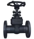
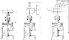
1.2 Construction:
The gate valve body is self-sealing or press seal gate valve. The connection method of the valve cover and the valve body is to use the upward pressure of the medium in the valve to force the sealing packing to be compressed to achieve the purpose of sealing. Gate valve sealing packing is sealed with high-pressure asbestos packing with copper wire.
The gate valve structure is mainly composed of the valve body, bonnet, frame, valve stem, left and right valve flaps, packing sealing device, etc.
The valve body material is divided into carbon steel and alloy steel according to the pressure and temperature of the pipeline medium. Generally installed in the valve of superheated steam system, t> 450 ℃ or more, the valve body is alloy material, such as boiler exhaust valve. For the valve installed in the water supply system or the pipeline with medium temperature t≤450 ℃, the valve body material is carbon steel.
Gate valves are generally installed on DN ≥ 100 mm soda pipes. The nominal diameter of the gate valve of the WGZ1045 / 17.5-1 boiler in the first phase of Zhang shan includes DN300, DNl25 and DNl00.
2. Maintenance technology of gate valve
2.1 Valve disintegration:
2.1.1 Remove the fixing bolts of the upper frame of the bonnet, the nuts of the four bolts on the lifting bonnet should be unscrewed, turn the stem nut counterclockwise to disengage the valve frame from the valve body, and then hang the frame with a lifting tool , Put it in the right place. The stem nut part is to be disassembled for inspection.
2.1.2 Take out the retaining ring at the sealing ring of the valve body and press down the bonnet with a special tool to make a gap between the valve cover and the ring. Then take out the quadruple ring in sections. Finally, use a lifting tool to lift the valve cover together with the valve stem and valve flap out of the valve body. Place it on the maintenance site, and pay attention to prevent damage to the flap joint surface.
2.1.3 Clean the inside of the valve body, check the joint surface of the valve seat, and determine the maintenance method. Cover the disassembled valve with a special cover or cover, and affix the seal.
2.1.4 Loosen the hinge bolt of the stuffing box on the valve cover. The packing gland is loose, and the valve stem is unscrewed.
2.1.5 Disassemble the upper and lower splints of the valve disc frame, take out the left and right valve flaps, and keep the internal gimbal and gasket. Measure the total thickness of the gasket and make a record.
2.2 Repair of valve components:
2.2.1 The joint surface of the valve seat of the gate valve should be ground with a special grinding tool (grinding gun, etc.). Grinding sand or emery cloth can be used for grinding. The method is also from coarse to fine, and finally polished.
2.2.2 The flap joint surface can be polished by hand or by grinding machine. If the surface has deep pits or grooves, it can be sent to a lathe or grinder for micro-processing. After all are leveled and polished.
2.2.3 Clean the valve cover and sealing packing, remove the rust on the inner and outer walls of the packing pressure ring, so that the pressure ring can be smoothly inserted into the upper part of the valve cover, which is convenient for compacting the sealing packing.
2.2.4 Clean the packing in the stem packing box, check whether the inner packing seat ring is intact, the clearance between the inner hole and the cutting rod should meet the requirements, and the outer ring and the inner wall of the packing box should not be jammed.
2.2.5 Clean the rust of packing gland and pressure plate, the surface should be clean and intact. The gap between the inner hole of the gland and the cutting rod should meet the requirements, and the outer wall and the stuffing box should not be jammed, otherwise repairs should be performed.
2.2.6 Loosen the hinge bolt, check that the screw part should be intact and the nut is intact, and it can be gently turned to the root of the bolt by hand, and the pin shaft should be rotated flexibly.
2.2.7 Clean the rust on the surface of the valve stem, check for bending, and straighten if necessary. The trapezoidal thread part should be intact, without breakage and damage, and coated with lead powder after cleaning.
2.2.8 Clean the Sihe ring, the surface should be smooth. The surface must not have burrs or curling.
2.2.9 The fastening bolts should be cleaned, the nuts should be intact and the rotation should be flexible, and the threaded parts should be coated with lead powder.
2.2.10 Clean the stem nut and internal bearing:
①Remove the fixing screw of the stem nut lock nut and the housing, and unscrew the lock screw in the counterclockwise direction.
② Take out the stem nut and bearing, disc spring, and clean it with kerosene. Check whether the bearing rotates flexibly and whether the disc spring is cracked.
③ Clean the stem nut, check whether the inner bushing ladder screw is intact, and the fixing screw with the shell should be firm and reliable. Liner wear should meet the requirements, otherwise it should be replaced.
④Coat the bearing with butter and put it into the stem nut. The disc springs are combined as required and reloaded in sequence. Finally, lock with a lock nut, and then fix it firmly with screws.
2.3 Assembly of gate valve:
2.3.1 Put the polished right and left valve flaps on the stem clamp ring and fix it with the upper and lower clamping plates. The gimbal should be placed inside, and the adjustment gasket should be added according to the maintenance situation.
2.3.2 Insert the valve stem together with the valve disc into the valve seat for testing and inspection. After the valve disc and the valve seat sealing surface are in full contact, ensure that the valve disc sealing surface is higher than the valve seat sealing surface and meet the quality requirements. Thickness of the shim to the top until it is suitable, and sealed with anti-return pad to prevent detachment.
2.3.3 Clean the valve body and wipe the valve seat and disc. Then put the valve stem and valve disc into the valve seat and install the valve cover.
2.3.4 Install the sealing packing at the self-sealing part of the valve cover as required. The packing specifications and the number of turns should meet the quality standards. The upper part of the packing is pressed with a pressure ring and finally closed with a cover plate.
2.3.5 Assemble the quadruple ring section by section, and use the retaining ring to raise the anti-off, and tighten the nut of the valve cover lifting bolt.
2.3.6 Fill the packing as required to fill the valve stem seal packing box, put it into the gland and pressure plate, and tighten it with a hinge screw.
2.3.7 Reinstall the bonnet frame, turn the upper stem nut to make the frame fall on the valve body, and fasten it with a connecting bolt to prevent it from falling out.
2.3.8 Install the electric drive device of the valve; the top part of the connecting part should be screwed tightly to prevent detachment, and manually test whether the cutting door switch is flexible.
2.3.9 The valve nameplate is clear, intact and correct. The maintenance records are complete and clear; and the experience is acceptable.
2.3.10 Insulation of pipelines and valves is complete, and the maintenance site is cleaned.
3. China pressure seal gate valve supplier's quality standards for gate valve maintenance
3.1 Valve body:
3.1.1 The valve body shall be free from defects such as trachoma, cracks and erosion, and shall be dealt with in time after discovery.
3.1.2 There should be no debris in the valve body and pipeline, and the entrance and exit are unblocked.
3.1.3 The thread plug at the bottom of the valve body should ensure a reliable seal and no leakage.
3.2 Valve stem:
3.2.1 The curvature of the valve stem should not be greater than 1/1000 of the total length, otherwise it should be straightened or replaced.
3.2.2 The trapezoidal thread part of the valve stem should be intact, without breakage, snapping and other defects, and the amount of wear should not exceed 1/3 of the thickness of the trapezoidal thread.
3.2.3 The surface is smooth and free of rust, and there is no flake corrosion and surface delamination on the sealing contact with the packing. Those with a uniform corrosion point depth ≥0.25 mm should be replaced with a new one. The finish should be guaranteed above ▽ 6.
3.2.4 The connecting thread should be intact and the pin fixed reliably.
3.2.5 The cutting rod and the cutting rod nut should be combined to rotate flexibly, without jamming during the whole stroke, and the thread should be coated with lead powder for lubrication protection.
3.3 Packing seal:
3.3.1 The pressure and temperature of the packing used shall meet the requirements of the valve medium, and the product shall be accompanied by a certificate of conformity or necessary test identification.
3.3.2 The packing specifications shall meet the size requirements of the sealed box, and shall not be replaced by oversized or undersized packings. The height of the packing shall meet the size requirements of the valve, and a heat tight margin shall be set aside.
3.3.3 The filler interface should be cut into an oblique shape with an angle of 45 °. The interface of each circle should be staggered by 90 ° -180 °. The length of the filler after cutting should be appropriate. There should be no gaps or overlaps in the interface of the filler box phenomenon.
3.3.4 The packing seat ring and packing gland should be intact, no rust, the stuffing box should be clean and smooth, the gap between the door rod and the seat ring should be 0.1-0.3 mm, and the maximum should not exceed 0.5 mm The gap between the outer periphery and the inner wall of the stuffing box is 0.2-0.3 mm, and the maximum is not more than 0.5 mm.
3.3.5 After the hinge bolt is tightened, the pressure plate should be kept straight and the tightening force is even. The packing gland and the inner hole of the pressure plate should be consistent with the gap around the valve stem. The packing gland pressed into the packing chamber should be 1/3 of its height dimension.
3.4 Sealing surface:
3.4.1 After repairing, the sealing surface of the valve disc and valve seat should be free of spots and grooves, the contact part should occupy more than 2/3 of the width of the valve flap, and the surface finish should reach more than ▽ 10.
3.4.2 Assemble the test valve flap. After inserting the valve flap into the valve seat, ensure that the valve core is 5-7 mm higher than the valve seat to ensure the tightness.
3.4.3 When assembling the left and right flaps, the self-adjustment should be flexible and the anti-off device should be intact and reliable. 3.5 Valve stem nut:
3.5.1 The internal bushing thread should be intact, and there should be no broken or disordered buckles, and the fixation with the outer shell should be reliable and free of looseness.
3.5.2 All bearing components should be intact and flexible in rotation. No cracks, rust, heavy skin and other defects on the surface of the inner and outer shells and steel balls.
3.5.3 Disc springs should be free of cracks and deformation, otherwise they should be replaced with new ones. 3.5.4 The fixing screws on the surface of the lock nut shall not be loose. The stem nut rotates flexibly, and the axial clearance is guaranteed but not greater than 0.35 mm.
4. Gate valve repair process and quality standards please download attachment.
 Gate valve repair process and quality standards.pdf