 +86 512 68781993


Analysis of the failure of the control valve positioner
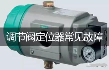
Valve positioners can be divided into: pneumatic valve positioners, electrical valve positioners and intelligent valve positioners. They are the main accessories of the control valve. They are usually used in conjunction with the pneumatic control valve. It receives the output signal of the regulator and then Its output signal is used to control the pneumatic control valve. When the control valve is actuated, the displacement of the valve stem is fed back to the valve positioner through the mechanical device, and the valve position status is transmitted to the upper system through electrical signals.
As the most precise part of the entire regulating valve, the valve positioner has the highest incidence of failures. Once a failure occurs, it will affect the operation of the entire system. Especially for high pressure control valve .Therefore, for the on-site instrument staff, learn more about this aspect. The knowledge is very necessary!
Common faults of pneumatic valve positioner
1. There is an input signal but the output is small or no
Due to excessive adjustment of the stroke fine-tuning screw of the positioner, the torque motor coil is unsoldered, just solder the lead.
The internal wire of the torque motor coil is broken or burned out due to overcurrent; use a multimeter to measure the resistance of the coil. Normally, it should be about 250Ω. If the deviation is too large, replace the coil.
The signal wire is in poor contact; check the wiring terminals to eliminate looseness.
The signal wire is connected reversely: check the (+) (-) terminal wiring to see if it is connected reversely.
The position of the nozzle baffle is incorrect: readjust the parallelism and see the output change.
The nozzle fixing screw is loose: Tighten the nozzle fixing screw to meet the stroke requirements.
The amplifier is faulty; check whether the amplifier is faulty or replace it.
Air blockage: Use Ф0.12 needle to remove dirt.
Exhaust hole blocked: There is a nozzle exhaust hole in the center of the base of the positioner. If it is blocked carelessly, the positioner will stop working.
The baffle lever connection spring is deformed or broken; open the positioner cover to replace it.
The permanent magnet is placed in the wrong position. Change the pole of the permanent magnet to see if the valve moves.
The feedback lever falls off; readjust the parallelism to see the valve action.
Feedback lever range fixed pin offset: adjust the pin to meet the travel requirements.
The hand wheel of the regulating valve with hand wheel is not hit to the middle position; check the position of the hand wheel and readjust it to the middle position.
Loose cam or improper position; tighten the cam or readjust the cam position.
Baffle lever connection spring stiffness is not enough: change (+) (-) polarity wiring, adjust the distance between baffle and nozzle to meet the travel requirements (in this case, the regulator action mode needs to be changed).
2. Output pressure oscillation
Dirt in the amplifier: Remove dirt in the amplifier.
Air leakage in the output pipeline or membrane head: eliminate air leakage and make the valve move smoothly.
The membrane head diaphragm is aging: just replace the aging diaphragm.
The position of the permanent magnet is wrong: readjust the parallelism of the permanent magnet to eliminate the instability of the magnetic circuit.
The screw fixing the feedback lever is loose: tighten the fixing screw to eliminate valve vibration.
Large AC component of the input signal: Eliminate the AC component or connect a capacitor in parallel at the input. Filter out AC interference.
Dirt on the back pressure air path: eliminate dirt and troubleshoot.
The valve stem is loose in the radial direction: check and repair the regulating valve.
3. There is output when there is no input
Partially blocked back pressure: clear the blocked dirt.
"The position of the automatic and manual switch is improper. Turn the "automatic and manual switch" clockwise to the "automatic" position.
4. Poor accuracy
The nozzle and baffle are not well adjusted: re-adjust the parallelism or nozzle fixing screws to meet the accuracy requirements.
Air leakage in back pressure gas path; eliminate air leakage.
Large radial displacement of the regulating valve: overhaul the regulating valve.
Improper adjustment of the zero adjustment screw: Re-adjust the zero adjustment screw to meet the accuracy requirements.
The feedback lever and the fixed pin position are wrong: adjust the pin position according to the stroke requirements again.
Common faults of electric valve positioner
1. Inaccurate zero point and range
Due to inaccurate debugging during the installation process of the positioner, on-site vibration, temperature changes, changes in the valve stem stroke of the control valve, changes in the position of the feedback lever, etc., the minimum opening and maximum opening of the control valve are inconsistent with the signal from the control room. As a result, the signal output by the valve positioner cannot make the regulating valve fully open and close, resulting in large leakage and limited quantities. In the on-site adjustment of the positioner, it is necessary to first ensure that the regulating valve operates well, the feedback system is installed firmly and operates well, and then the standard signal is used to adjust. Make the stroke of the regulating valve consistent with the control signal.
2. The orifice is blocked
Loot blocks the orifice. The positioner has no output signal, causing the regulating valve to not operate.
3. There is stolen goods between the nozzle and baffle
Affected by the on-site environment, a layer of dust will adhere to the positioner after a period of use, which affects the back pressure of the nozzle baffle, thereby affecting the output of the positioner. Cause the control valve to be unstable and oscillate.
4. Poor sealing
Various fastening nuts and sealing gaskets of the positioner that have been used for a long time are prone to loosening and aging, which will cause the positioner to leak air. So that the regulating valve cannot be fully opened and closed, the valve position is unstable, and regulation oscillation occurs.
5. Feedback lever failure
During long-term operation, the feedback rod tightening nut gradually loosens or even falls off, causing the feedback rod to become loose, skewed, jammed with the fixed parts, and fall off. The control valve is slow to move, fluctuates frequently, and the control valve is limited or even out of control. The limit spring on the feedback board falls off, or the feedback lever comes out of it, resulting in poor contact between the feedback lever and the feedback board, resulting in lag, and frequent actions of the regulating valve. It is difficult to stabilize the controlled parameters, especially in the temperature control that requires accurate valve action.
6. The fixing nut is loose
If the fixing nut of the positioner is not installed firmly, it will loosen, causing the positioner to skew, affecting the action of the feedback lever, and causing jamming. Makes the control valve unstable, causing position limit and other phenomena. The fastening screws of various springs in the positioner are loosened in a vibration environment, which changes the preload of the spring and affects the tension and state of the spring. The zero point range of the positioner is changed, the positioner is not linear, so that the regulating valve cannot be fully opened and closed, and the regulating valve action is not linear.
7. The position of the permanent magnet changes
Due to the external force, the positions of the two magnets are changed and the position of the magnetic field is changed. The force of the coil is unbalanced, and the output of the positioner is not linear, which makes the action of the regulating valve not linear. The magnet attracts impurities such as iron pins, forming a jam and obstructing the movement of the baffle, making the output of the positioner inaccurate, so that the action of the regulating valve is inconsistent with the control signal
Common faults of intelligent valve positioner
1.Reasons for the slow output speed of the positioner :
1) Leakage of the input air chamber; 2)
Blockage of the constant orifice; 3) Leakage of the air supply pipeline; 4) The
baffle is scratched or poorly positioned.
Take measures:
1) replace the damaged diaphragm; 2) clean
the orifice; 3) detect the leak and deal with it; 4) replace the baffle or
readjust it.
2. The positioner has no output pressure (the baffle does
not operate after the input signal).
Reasons:
1) The positive and negative stage wiring is
wrong; 2) The air source five pressure; 3) The magnetoelectric component coil
is broken.
Take measures:
1) Re-wiring; 2) Input the specified air
pressure; 3) Connect the broken wire of the coil.
3. The positioner has no output pressure
(the input signal baffle has action)
Reasons:
1) The gap of the nozzle baffle is too
large; 2) The baffle surface is scratched; 3) The zero position is improperly
adjusted; 4) The amplifier gas circuit is blocked; 5) The nozzle orifice is
blocked; 6) The zero adjustment spring is too soft.
Take measures:
1) Loosen the fastening screw, adjust the
nozzle baffle gap when inputting the maximum signal, so that the pressure gauge
value reaches 0.1~0.11Mpa, after fastening the screw, perform a negative
inspection; 2) replace the baffle; 3) Input the minimum signal, turn the
zero-adjusting screw to move the carriage to the left, and tighten the zero-adjusting
spring until the actuator starts to move; 4) Check the air circuit; 5) A: Use
fine steel wire for dredging, B: Replace the air filter to reduce pressure The
filter element of the valve; 6) Replace the zero spring.
4. The output pressure of the positioner does not decrease
after the input current signal changes.
Reasons:
1) The installation
position is not suitable, so that the gap between the nozzle and the baffle is
too small; 2) There is dirt on the nozzle end or the contact
part of the baffle and the nozzle, which reduces the actual gap.
Small; 3) The screw on the nozzle base is not tightened after adjustment, which
causes the gap to change; 4) The constant air flow hole parts fall off, causing
the orifice to become larger.
Take measures:
1) Readjust the gap between
the nozzle and the baffle; 2) Remove the dirt on the nozzle end or the contact
part of the baffle and the nozzle; 3) Tighten the screws on the nozzle base; 4)
Check the constant orifice and reinstall it Falling parts.
5.Reasons for zero misalignment :
1) The zero adjustment
screw is loose; 2) The diaphragm of the input air chamber is leaked; 3) The
fastener is loose after the stroke adjustment; 4) The cam is loose.
Take measures:
1) Tighten the zero
adjustment screw and readjust the zero point; 2) Fasten the amplifier screw and
replace the damaged diaphragm; 3) Re-tighten the stroke adjustment piece; 4)
Fasten the cam.
6.Reasons for misalignment of positioning output :
1) Leakage in the input air
chamber; 2) Loose cam; 3) Loose main lever fulcrum plate and spring leaf
screws.
Take measures:
1) Replace damaged parts or
tighten seal leakage; 2) Re-tighten the cam; 3) Re-tighten the screws.Cowinns
can supply 2500LB control valve .And we have good experience on
control valve technical and maintain projects.