 +86 512 68781993


Manufacturing technology of ball valve sphere
The ball is the opening and closing part of the ball valve, also known as the core or ball. The ball rotates around the center line of the valve body to open and close the ball valve. The ball valve can cut off, adjust, distribute and change the flow direction of the medium in the pipeline. Ball valves have many advantages and are a new type of valve widely used in recent years. Ball valves with different functions often have different balls.
Comparison of valve ball forming methods
(1) Casting method
Casting method is a traditional processing method. It requires a complete set of equipment for smelting and pouring, as well as larger workshops and more workers. The investment is large, the process is large, the production process is complex, and the environment is polluted. The skill level of the workers in each process directly affects the quality of the product. The problem of leakage of the pores of the valve ball has not been completely solved, and the blank machining allowance is large, and the waste is large. It is often found that the casting defects make it scrapped during the processing. Product costs have increased and quality cannot be guaranteed.
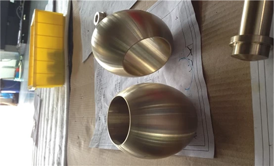
Ball for ball valve C95800
(2) Forging method
Forging method This is another method used by many domestic valve companies. It has two processing methods: one is to cut and heat forge into a spherical solid blank with round steel, and then perform mechanical processing. The second is to mold the circular stainless steel plate on a large press to obtain a hollow hemispherical blank, which is then welded into a valve sphere blank for mechanical processing. This method has a high material utilization rate, but a large power is required. The presses and heating furnaces and argon welding equipment.
Free forging
It refers to a free forging after forging the metal blank placed in the device a good heating iron Di (the lower) between, applying an impact force or pressure, such that the blank is plastically deformed directly, to obtain raw Method for processing producing forgings. Classification: Manual free forging, hammer free forging, hydraulic press free forging
Advantages: strong applicability, flexibility, short cycle, the only method for extra large forgings
Disadvantages: low precision, large machining allowance, low efficiency, high labor intensity
Die forging
The formal term of die forging is called model forging. The billet is heated and placed in a forging die fixed on the die forging equipment to forge the final shape.
Die forging equipment: In industrial production, most of them use hammer forging. Steam-air hammer, with a tonnage of 5KN~300KN (0.5~30t), the most common die forging on the press is the hot die forging press.
Forging ratio
Forging ratio: refers to the ratio of the cross-sectional area of the blank (metal) before and after forging. The calculation method and method are also different for different processes.
When drawing, the forging ratio is y=F0/F1 or y=L1/L0 F0, L0—the cross-sectional area and length of the ingot or billet before drawing; F1, L0—the cross-sectional length of the ingot (slab) after drawing area.
Forging ratio during upsetting, also called upsetting ratio or compression ratio, its value is y=F1/F0 or y=H0/H1 F0, H0— the cross-sectional area and height of the ingot or billet before upsetting, F1, H1 —The cross-sectional area and height of the ingot or billet after upsetting.
Forging temperature
a. Initial forging temperature: The initial forging temperature can be considered as the maximum temperature at which steel or alloy is allowed to be heated in the furnace.
b. Final forging temperature: The blank material of the valve parts needs to have strong plasticity before the end of forging, and the recrystallized structure will be obtained after forging.
(3) Spinning method
The metal spinning method is an advanced processing method with less and no chips. It belongs to a new branch of pressure processing. It combines the characteristics of forging, extrusion, rolling and rolling, and has high material utilization (up to 80-90%) ), saving a lot of processing time (1-5 minutes forming), the material strength can be doubled after spinning. Due to the small-area contact between the rotating wheel and the workpiece during spinning, the metal material is in a two-way or three-way compressive stress state, which is easy to deform. Under a small power, a higher unit contact stress (up to 25- 35Mpa), therefore, the equipment is light in weight and the total power required is small (less than 1/5 to 1/4 of the press). It is now recognized by the foreign valve industry as an energy-saving valve sphere processing technology program. It is suitable for processing other hollow rotating parts. Spinning technology has been widely used and developed at a high speed abroad. The technology and equipment are very mature and stable, and the automatic control of the integration of mechanical, electrical and hydraulic is realized. At present, spinning technology has also been greatly developed in my country and has entered the stage of popularization and practicality.
· Common materials and grades of spheres
· A. Carbon steel
· ASTM A105
· ASTM A350 LF2
· ASTM A694 F60
· B. Low alloy steel
· ASTM A322 4130 (AISI 4130)
· ASTM A322 4140 (AISI 4140)
· C. no stainless steel
· C.1 Ferritic stainless steel: ASTM A182 F429 F430
· C.2 Martensitic stainless steel: ASTM A182 F6a Class1/Class2/Class3/Class4 GB/T 1220 12Cr13
· C.3 Austenitic stainless steel: ASTM A182 F316 ASTM A182 F304
· C.4 Duplex stainless steel: ASTM A182 F51 F53 F55 F60
· C.5 Precipitation hardening stainless steel: ASTM A705 17-4PH
· D. Nickel-based alloy
· ASTM B564 Moenl400
· ASTM B564 NO6625(Inconel625)...
· National standard :
· ASTM: American Society for Testing and Materials Standard
· AISI: American Iron and Steel Institute Standard
· GB: Chinese National Standard
· JIS: Japanese Industrial Standard
·
· Material writing: national standard + standard number + material grade
· Sphere technical conditions
Selection of cross-section diameter of ball valve passage
When designing and calculating the ball valve, the diameter of the passage of the ball must be determined first, so as to be the basis for other parts of the calculation. The minimum diameter of the sphere channel must meet the requirements of the corresponding standards.
When designing the national standard ball valve, the minimum diameter of the full-bore ball valve should comply with the GB/T 19672-2005 "Pipeline Valve Technical Conditions" or GB/T 20173-2006 "Oil and Natural Gas Industry-Pipeline Transportation System-Pipeline Valve" standard requirements.
When designing the American standard ball valve, the minimum diameter of the full-bore ball valve should comply with the standard requirements of AP16D—2008/IS014313: 2007 "Oil and Natural Gas Industry-Pipeline Transportation System-Pipeline Valve".
For reduced diameter ball valve standards, for valves with a nominal size of DN≤300mm (NPSl2in), the aperture of the valve's nominal size is reduced by one specification, and the inner diameter is specified in the standard; for valves with a nominal size of DN350 (NPSl4) ~ N600 (NPS24), the valve The nominal size of the aperture is reduced by two specifications, according to the inner diameter specified by the standard; for the valve of the nominal size DN>600mm (NPS24in), it is agreed with the user. For ball valves without standard regulations, usually the cross-sectional area of the ball channel should not be less than 60% of the rated cross-sectional area of the pipe, and it is designed to be reduced in diameter, which can reduce the structure of the valve, reduce weight, and reduce the role of the sealing surface of the valve seat Force and opening and closing torque. Generally, the ratio of the nominal valve size DN to the ball channel diameter d is equal to 0.78. At this time, the resistance of the ball valve will not be too large.
Common heat treatment types of spheres
ASTM A105: Normalizing treatment
ASTM A350 LF2: Quenching and tempering treatment
ASTM A694 F60: Quenching and tempering treatment
ASTM A322 4130/4140: Quenching and tempering treatment
ASTM A182 F6a CLASS2: quenching and tempering (secondary tempering)
ASTM A182 F304/F316/F51/F53/F55/F60: solution treatment
ASTM A705 17-4PH: precipitation hardening treatment (quenching + secondary artificial aging)
Ball surface plating
1. Why electroless plating?
Purpose: Improve the wear resistance or corrosion resistance of the ball in actual use
2.Why is the amount of electroplating of carbon steel materials the largest?
Carbon steel is easy to rust, and its surface hardness is also low. In order to prevent the surface of carbon steel from rusting and save costs, the amount of carbon steel plating is the largest
3.Why do stainless steel materials need to be electroplated?
The main purpose is to improve the surface hardness of the sphere, thereby improving the wear resistance in use.
4. Common types (classification)
1. Electroless nickel and phosphorus plating (reference standard ASTM B733)
1.1 According to the type of coating alloy:
o Class I: P no requirement
o Type II: lower phosphorus (1~3%)
o Class III: Low Phosphorus (2~4%P): Hardness of plating state 620-750HK
o Category IV: Medium Phosphorus (5~9%P): Widely used in occasions meeting wear resistance and corrosion resistance
o Type V: High Phosphorus (>10%): It has excellent salt spray resistance and acid resistance in various occasions. The coating with phosphorus content greater than 11.2% is considered to be magnetic.
1.2 Classification according to thickness usage conditions:
o SC0 0.1μm-minimum use conditions
o SC1 5μm-light load conditions
o SC2 13μm-moderate use conditions
o SC3 25μm-moderate use conditions
o SC4 75μm-severe use conditions
1.3 Classification by heat treatment after plating:
o Category 1-As deposited, without heat treatment
o Category 2-heat treatment at 260~400 ℃ to produce a minimum hardness of 850HK
Category 3-Heat treatment at 180~200 ℃ for 2~4 hours to improve the coating adhesion of steel and prepare for elimination of hydrogen embrittlement.
Category 4-Heat treatment at 120~130 ℃ for more than 1 hour to increase the adhesion (bonding force) of aluminum alloy and carburized steel.
Category 5-Heat treatment at 140~150 ℃ for more than 1 hour to improve the coating adhesion of aluminum, non-age hardening aluminum alloy, copper, and copper alloy.
Note: Generally, the hardness requirements of the sphere heat treatment are recommended to be 500~650HV or 600~850HV or above 850HV, choose among the three