 +86 512 68781993


Common Valve Installation Knowledge
Common Valve Installation Knowledge
Pre-installation Inspection of Valves
1.Carefully check and verify whether the valve model and specifications meet the design drawing requirements.
2.Check if the valve stem and disc operate flexibly, ensuring there is no jamming or misalignment.
3.Inspect the valve for any damage and ensure that the threads of threaded valves are straight and intact.
4.Verify the secure connection between the valve seat and the valve body, as well as the connections between the valve disc and seat, valve cover and body, and valve stem and disc.
5.Ensure that the valve gaskets, packing, and fasteners (bolts) are suitable for the working medium's properties.
6.For old or long-unused pressure-reducing valves, disassemble them and clean out dust, sand, and other debris with water.
7.Remove the port cover and check the seal; the valve disc must be tightly closed.
Pressure Testing of Valves
Low-pressure, medium-pressure, and high-pressure valves must undergo strength tests and leak-tightness tests. Alloy steel valves should also have their bodies individually analyzed using spectrometry to verify the material composition.
Valve Strength Test
The strength test of a valve is conducted with the valve open to check for leaks on the exterior surface of the valve. For valves with a PN ≤ 32MPa, the test pressure is 1.5 times the nominal pressure, and the test duration should not be less than 5 minutes. The valve is considered qualified if there are no leaks at the shell body and the packing gland.
Valve Tightness Test
This test is performed with the valve fully closed to check for leaks at the sealing surface. Except for butterfly valves, check valves, bottom valves, and throttle valves, the test pressure is generally conducted at the nominal pressure. If the working pressure can be determined, the test can also be performed at 1.25 times the working pressure. The valve is qualified if there are no leaks at the valve disc sealing surface.
China high pressure dual plate check valve manufacturer will give recommendations for the dual plate check valve.
General Regulations for Valve Installation
1.The position of the valve should not interfere with the operation, disassembly, and maintenance of the equipment, pipeline, and valve body itself, while also considering the aesthetic appearance of the assembly.
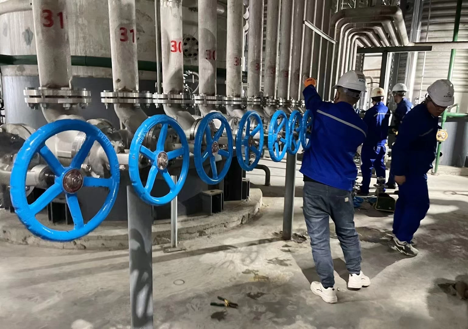
2. Valves on horizontal pipelines should be installed with the stem facing upwards or at a certain angle, but not with the handwheel facing downwards. Valves on high-altitude pipelines can have their stems and handwheels installed horizontally, with a chain hanging from a lower vertical position to remotely control the opening and closing of the valve.
3. Arrange symmetrically and neatly; for valves on vertical pipelines, under process-allowable conditions, the valve handwheel is most suitable for operation at chest height, generally between 1.0-1.2m from the ground, and the stem must be installed in the direction of the operator.
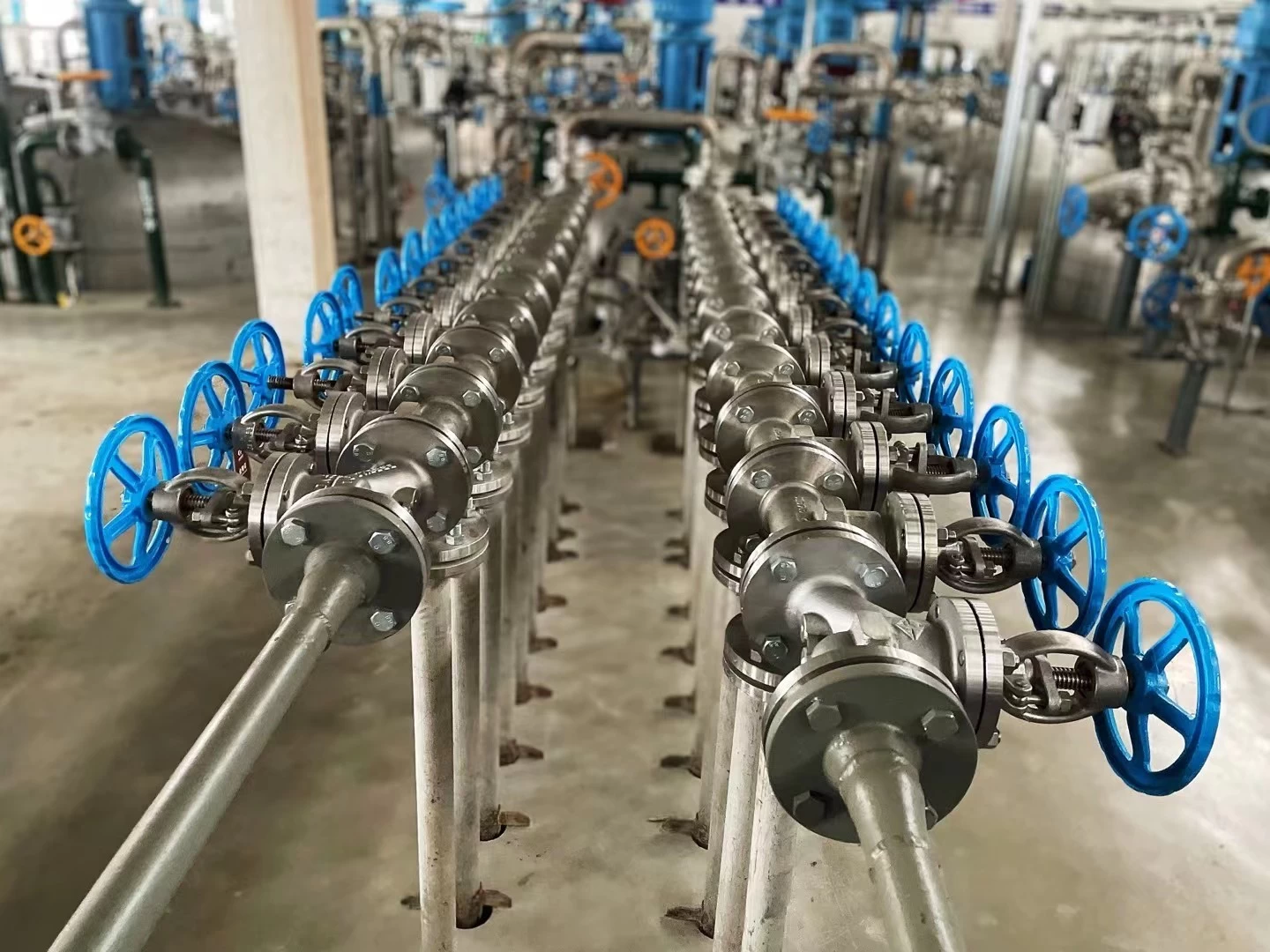
4. For valves on parallel vertical pipelines, it is best to have the same centerline elevation, and the net distance between handwheels should not be less than 100mm; valves on parallel horizontal pipelines should be installed staggered to reduce pipeline spacing.
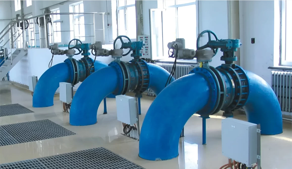
5. When installing heavier valves on equipment such as pumps and heat exchangers, a valve support should be provided; for valves that are frequently operated and installed more than 1.8m above the operating surface, a fixed operating platform should be provided.
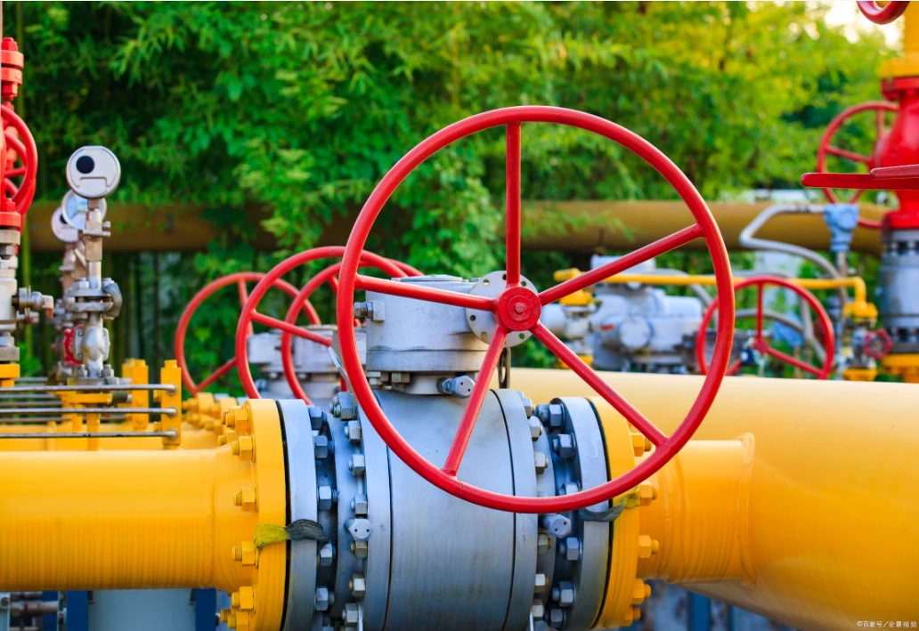
6. If the valve body has an arrow mark, the direction of the arrow indicates the flow direction of the medium. When installing the valve, attention should be paid to ensuring that the arrow points in the same direction as the flow of the medium inside the pipeline.
7. When installing flanged valves, it is necessary to ensure that the two flange end faces are parallel and concentric to each other, and double gaskets should not be used.
8. When installing threaded valves, to facilitate disassembly, one threaded valve should be equipped with one union. The setting of the union should consider the convenience of maintenance, and usually the water flow passes through the valve before passing through the union.
Attention Points for Valve Installation
1. The valve body is mostly made of cast iron, which is brittle, so it must not be subjected to heavy impacts.
2. When handling valves, they should not be thrown around casually; when lifting or hoisting valves, the rope should be tied to the valve body, and it is strictly forbidden to tie it to the handwheel, valve stem, or flange bolt holes.
3. Valves should be installed in the most convenient place for operation, maintenance, and repair, and it is strictly forbidden to bury them underground. For valves on direct-buried and trench pipelines, inspection wells should be set up to facilitate the opening, closing, and adjustment of the valves.
4. The threads should be ensured to be complete and undamaged, and the threads should be wrapped with hemp, smeared with lead oil, or wrapped with polytetrafluoroethylene raw material tape. When screwing, a wrench should be used to hold the hexagonal valve body that is screwed into one end of the pipe.
5. When installing flanged valves, pay attention to tightening the connecting bolts along the diagonal direction. The force applied should be even to prevent the gasket from shifting or causing deformation and damage to the valve body.
6. Valves should be kept closed during installation. For threaded valves close to the wall, it is often necessary to remove the valve stem, valve disc, and handwheel during installation to screw them in. When disassembling, the handwheel should be turned to keep the valve open before disassembly.
Installation of Common Valves
1. Gate Valve Installation
Gate valves, also known as sluice valves, control the opening and closing by using a sluice plate. They regulate the pipeline flow by changing the cross-sectional area and open and close the pipeline. Gate valves are mostly used for pipelines that require full opening or full closing operations on fluid media. There are generally no directional requirements for gate valve installation, but they should not be installed upside down.
2.Globe Valve Installation
Globe valves control the opening and closing by using a valve disc. They regulate the medium flow or cut off the medium passage by changing the gap between the valve disc and the seat, i.e., by changing the size of the channel section. The direction of fluid flow must be noted when installing globe valves. The principle that must be followed is that the fluid in the pipeline should flow from bottom to top through the valve hole, commonly known as "low in and high out," and should not be installed in reverse.
3.Check Valve Installation
Check valves, also known as counter-flow valves or one-way valves, are valves that automatically open and close under the action of pressure difference before and after the valve. Their function is to allow the medium to flow in only one direction and prevent the medium from flowing back against the direction. Check valves come in different structures, including lift check valves, swing check valves, and wafer butterfly check valves. Lift check valves are further divided into horizontal and vertical types. When installing check valves, the direction of the medium should also be noted and should not be installed in reverse.
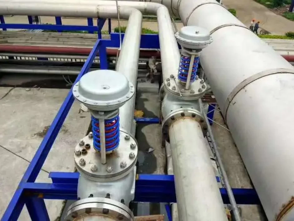
4.Pressure Reducing Valve Installation
Pressure reducing valves are valves that reduce the import pressure to a required export pressure through adjustment and automatically maintain the export pressure stable by relying on the energy of the medium itself.
From the perspective of fluid mechanics, a pressure reducing valve is a throttling element whose local resistance can change. That is, by changing the throttling area, the flow speed and kinetic energy of the fluid are changed, resulting in different pressure losses, thereby achieving the purpose of pressure reduction. Then, by adjusting the control and regulation system, the fluctuation of the pressure behind the valve is balanced with the spring force, keeping the pressure behind the valve constant within a certain error range.
Installation of Pressure Reducing Valves
1.Vertically installed pressure reducing valve groups are generally set along the wall at a suitable height from the ground; horizontally installed pressure reducing valve groups are generally installed on permanent operating platforms.
2.Use steel profiles to load into the wall outside the two control valves (commonly used for globe valves) to form a bracket, and the bypass pipe is also clamped on the bracket, leveling and aligning.
3.Pressure reducing valves should be installed upright on horizontal pipelines, should not be inclined, and the arrow on the valve body should point in the direction of medium flow, should not be installed in reverse.
4.Globe valves and high and low-pressure pressure gauges should be installed on both sides to observe the pressure changes before and after the valve. The pipeline diameter after the pressure reducing valve should be 2#-3# larger than the valve inlet diameter, and a bypass pipe should be installed for maintenance.
5.The equalizing pipe of the diaphragm-type pressure reducing valve should be connected to the low-pressure pipeline. A safety valve should be set on the low-pressure pipeline to ensure the safe operation of the system.
6.When used for steam pressure reduction, a drain pipe should be set. For pipeline systems with high purification requirements, a filter should be set before the pressure reducing valve.
7.After the installation of the pressure reducing valve group is completed, the pressure reducing valve and safety valve should be tested, flushed, and adjusted according to the design requirements, and a mark should be made after adjustment.
8.When flushing the pressure reducing valve, close the pressure reducer inlet valve and open the flush valve for flushing.
Steam Trap Installation
The basic function of a steam trap is to quickly expel condensate, air, and carbon dioxide gas from the steam system while automatically preventing steam leakage to the greatest extent possible. There are many types of steam traps, each with different performance characteristics.
Based on the working principle of steam traps, they can be divided into the following three types:
Mechanical type: Actuated by changes in the height of the condensate level inside the steam trap, including:
Float type: The float is a closed hollow sphere.
Open upward float type: The float is a bucket shape with an opening facing upwards.
Open downward float type: The float is a bucket shape with an opening facing downwards.
Thermostatic type: Actuated by changes in liquid temperature, including:
Bimetallic strip: The sensitive element is a bimetallic strip.
Steam pressure type: The sensitive element is a corrugated tube or a box filled with volatile liquid.
Thermodynamic type: Actuated by changes in the thermodynamic properties of the liquid.
Disc type: Due to the different flow speeds of liquid and gas under the same pressure, the different dynamic and static pressures drive the disc valve plate to act.
Pulse type: Due to the condensate of different temperatures passing through two serial connected orifice plates