 +86 512 68781993


Valve packing technology
The scope of fugitive leakage prevention and control includes both the leakage of harmful and harmful substances-to prevent pollution of the environment, and the leakage of steam and other low-temperature inert media-to prevent lowering production efficiency. Preventing leaks from the root cause should be the best choice. Specifically, it requires a well-designed casing, reasonable selection of packing material and structure, and correct installation.
Usually four to six packing rings can be accommodated in the stuffing box, and the sealing element of the valve stem is as few as one to two, and as many as the riser structure, there may be seven packing rings. Packing rings can be made by braided or compression molding.
The miter method is recommended, because better end-binding effect can be obtained under the additional effect. It must be noted that each packing ring must completely surround the entire mandrel / stem; the best condition is that the tightness between the outside of the packing ring and the inner wall of the stuffing box is higher than the tightness between the packing ring and the valve stem degree. If the packing rope heads adjacent to each other are too long to cause stacking or too short to cause vacancies, the packing ring density will be uneven and become a potential leakage path. For some power plant pipeline valve, such as 4500LB Y-pattern power plant globe valve ,it must be strictly for packing assemble.
Compression and load
When installing the packing, each packing ring must be installed in place until the complete packing group is completed. This can ensure uniform axial stress distribution, reduce friction and leakage rate, reduce or even avoid the need to replace the packing or re-tighten the gland in the future, thereby extending the service life of the packing group.
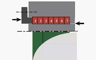
Figure 1
Conversely, if a set of five packing rings is installed at one time, the top packing ring closest to the gland follower receives the largest load, but the lowest packing ring closest to the process medium receives a small load, which can even can be ignored. The reason is that the packing ring will reduce the axial load, and the effect of the bottom packing ring to prevent the leakage of the medium will be worse, whether it is cutting and winding or molding the packing. Another situation is that the load applied to the top of the packing ring is too large, resulting in excessive friction when the valve stem rotates, and even damage the packing group (Figure 1). From some data, it can be seen that if the installation operation is properly regulated, the maximum degree of stress relaxation of the packing group after 100 mechanical cycles is not more than 20%. But if the installation is not correct, the stress will even be reduced by about 60%, so that the sealing performance is no longer reliable.
Temperature limit
Only in a specific temperature range can the packing and sealing material have the best performance. For example, the temperature range of polytetrafluoroethylene (PTFE) is between minus 101 ° C and 232 ° C. If it is used in a higher temperature environment, its molecular structure may change, leading to the leakage of harmful gases, which will cause the valve stem to corrode, and even cause toxic PTFE flue gas to escape from the top of the gland follower.
Such smoke may even be carcinogenic. In addition, as the flue gas is released, the packing material will soften and the weight will be reduced, which will lead to leakage of harmful process media or product leakage. If flexible graphite is used, the applicable temperature range is naturally different. In an oxidizing atmosphere, it is generally between minus 196 ° C and 450 ° C.
Comprehensive consideration of material characteristics, such as the content of ash, chloride, sulfur, fluoride and other halogen compounds, as well as the loss of oxidation quality information provided by the manufacturer, can determine that graphite packing can reliably prevent fugitive leakage in the environment of up to 450 ° In the steam working condition where oxidation reaction does not occur, it can withstand up to 650 ° C. Flexible graphite and polytetrafluoroethylene (PTFE) are widely used in various media with a pH value of 0-14; graphite materials are also suitable for fire safety sealing in some cases.
Hazard and Risk Assessment
Before installing packing, a comprehensive hazard and risk assessment should be performed. First of all, it is necessary to properly isolate the valve to ensure safe construction. Operators should wear protective clothing and goggles as required. Use the packing removal tool to remove all the old packings from the stuffing box (Figure 2).
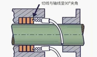
Figure 2
Use an inspection mirror to carefully check the valve stem for signs of corrosion and scratches, and make sure that the old packing has been completely removed. Renovate if necessary. Then measure the outer diameter of the stem, the inner diameter of the stuffing box, and the depth of the stuffing box cavity to accurately calculate the packing size.
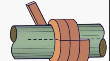
Figure 3
The calculation formula of the packing ring radius is ((OD-ID) / 2), and then calculate how many layers of packing ring thickness can match the depth of the stuffing box cavity. The packing material can be cut around the mandrel with the same diameter as the valve stem and cut vertically (in the radial direction); it can also be cut obliquely with a special cutting tool for packing. Care needs to be taken to avoid stretching the packing material along its length, and to prevent its cross-section from being deformed by compression. It should also be noted that the cutting surface must be neat and neat, and there must be no impurities or debris on the cutting surface.
Separate packing rings
The packing material must not be filled with stuffing boxes by winding the coil. Instead, the packing material is cut with a special cutting tool and made into an independent packing ring. The cut is 45º (mitered) (see Figure 6). In this way, you can use the load to obtain a better end surface bonding effect.
You need to check whether the size of each packing ring exactly matches the stuffing box; the interfaces of each ring are properly docked, and the inner wall of the stuffing box should be closely fitted to the maximum extent, and the braided material cannot be stretched to match the inner diameter. All subsequent packing rings must be the same size and cut as the first one.
Preformed packing rings are very common and do not require on-site cutting, so they are easy to install. First check the valve gland bolts, nuts and gaskets and replace them if damaged. Both bolts and nuts need to be greased. In order to effectively control fugitive leakage, a torque wrench must be used and the operating procedures provided by the packing supplier must be followed.
Turn the valve stem
Stuffing boxes must also be clean and free of impurities and grease. Put the first packing ring into the stuffing box and pay attention to the position of the interface. You should first insert the interface into the stuffing box and then the rest of the packing ring. If it is a flexible graphite molded packing ring, each ring should be stretched into a spiral shape (Figure 4) and then installed in place to avoid damage to the packing ring. Install one packing ring at a time, making sure that it has been compacted and seated in the stuffing box before installing the next one. If the gland follower is not long enough to reach the bottom of the stuffing box, a temporary tool or extension ring is required to install the packing ring.
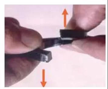
Figure 4
Unless otherwise specified, sealing elements must not be lubricated. Apply the load to the first installed packing ring in accordance with the manufacturer's instructions. Repeat the same steps for the next packing ring, only one can be installed at a time. The respective interfaces of any two adjacent packing rings must be at 90º and 180º positions (Figure 5).
After the installation is completed, the valve stem must be operated to cycle the valve between the open and closed positions three to ten times to ensure that the packing group is properly seated. For pneumatic Y-pattern steam drain globe valve it should be very carefully on packing. During this process, the packing group will loosen to some extent, so after the switch operation is completed, it should be re-tightened according to the parameters provided by the manufacturer to allow sufficient margin to offset future loosening. In the same way, after the valve is put into use under normal working conditions, the packing group should be tightened for the last time to reserve sufficient margin for future stress relaxation.
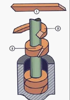
Figure 5
Avoid leaks
If the packing is installed correctly, the attenuation from axial stress to radial stress will be reduced. This helps the packing to maintain a reliable sealing performance for a longer period of time and a reasonable friction load distribution. On this basis, the fugitive leakage sealing performance of the valve and even the production efficiency will be significantly improved.
In the 1970s, it was acceptable if the valve packing leaked a few drops of liquid per minute. In the current era, the government's legislative orientation is to eliminate leaks, and it has introduced relevant regulatory regulations and procedures for finding, reducing and controlling valve leakage. In addition, manufacturers and end users require valves to pass various standard tests, such as ISO15848-1, API 624, and API 641.
The correct packing installation procedure is one of the factors that determine whether the sealing performance is qualified. The sealing performance is an important sign to judge whether the value of the valve supplier exceeds its peers.