Common malfunctions of pressure-reducing valves, troubleshooting methods, and maintenance management
Common malfunctions of pressure-reducing valves, troubleshooting methods, and maintenance management.
1. Common Malfunctions of Pressure-Reducing Valves
(1) The outlet pressure is almost equal to the inlet pressure, with no pressure reduction.
This malfunction is characterized by the inlet and outlet pressures of the pressure-reducing valve being nearly equal, with the outlet pressure not changing when the adjustment handle is rotated. The causes and troubleshooting methods are as follows.
a). The issue may arise due to burrs on the edges of the grooves on the main valve spool or valve body bore, debris trapped in the clearance between the main valve spool and the bore, or dimensional tolerance deviations of the spool or bore, resulting in hydraulic jamming that locks the spool in the fully open (max) position. This large opening prevents pressure reduction. Troubleshooting involves removing burrs, cleaning, and restoring the precision of the valve bore and spool as appropriate.
b). The malfunction may result from an overly tight fit between the main valve spool and the valve bore or scratches on the bore or spool during assembly, causing the spool to become stuck in the fully open position. In this case, select a reasonable clearance. For J-type pressure-reducing valves, the clearance is typically 0.007–0.015 mm. Before fitting, the valve bore can be appropriately polished, followed by matching the spool.
c). The short damping hole on the main valve spool or the valve seat hole may be blocked, causing the loss of automatic regulation functionality. The main valve spring force pushes the valve spool to the fully open position, resulting in a direct, unobstructed flow where the inlet pressure equals the outlet pressure. To resolve this, use a φ1.0 mm steel wire or compressed air to clear the damping hole, followed by cleaning and reassembly.
d). For J-type pressure-reducing valves, the damping component with a damping hole is press-fitted into the main valve spool. During operation, it may become dislodged if the interference fit is insufficient. Once dislodged, the pressure in the inlet and outlet chambers becomes equal (no damping). Since the force-bearing areas on the spool's upper and lower sides are equal, but the outlet chamber has a spring, the main valve spool remains in the fully open position, causing the outlet pressure to equal the inlet pressure. In this case, a new damping component with a slightly larger outer diameter should be machined and press-fitted back into the main valve spool.
e). For JF-type pressure-reducing valves, the oil drain hole is sealed with a plug when leaving the factory. If the valve is used without removing this plug, oil becomes trapped in the upper chamber (spring chamber) of the main valve spool, causing the spool to remain in the fully open position and preventing pressure reduction. A similar issue can occur with J-type inline valves. For J-type plate-mounted valves, this phenomenon may also occur if the L port is not connected to the oil reservoir during the design or installation of the mounting plate.
f). For J-type inline valves, it is easy to install the valve cover in the wrong direction (rotated by 90° or 180°) during disassembly and repair. This blocks the external drain port, preventing oil discharge and causing the same trapped oil issue described above, which keeps the main valve spool in the fully open position, preventing pressure reduction. To resolve this, ensure the valve cover is installed in the correct orientation during repair.
g). For JF-type pressure-reducing valves, if the end cap is installed incorrectly, it can cause the output oil port to be connected to the drain port, resulting in no pressure reduction. This should also be carefully checked.
(2) The outlet pressure is very low, and even when the pressure adjusting handwheel is tightened, the pressure cannot be increased.
a). The inlet and outlet ports of the pressure-reducing valve are reversed: for plate-type valves, this is due to an error in the mounting plate design; for inline valves, it is caused by incorrect pipe connections. The inlet and outlet ports of the J-type pressure-reducing valve are exactly opposite to those of the Y-type relief valve. Users should pay attention to the stamped markings near the oil ports on the valve (e.g., Pl, P2, L, etc.) or refer to the hydraulic component product catalog to avoid design or connection errors.
b). The inlet pressure is too low, and after passing through the throttle port of the pressure-reducing valve spool, the output pressure from the outlet is even lower. In this case, the cause of the low inlet pressure should be identified (e.g., a malfunction in the relief valve).
c). The downstream load of the pressure-reducing valve is too small, preventing pressure from building up. In this case, a throttling valve can be installed in series downstream of the pressure-reducing valve to resolve the issue.
d). The pilot valve (cone valve) may have poor contact or inadequate sealing due to debris trapped between the mating surfaces of the valve and the seat. Alternatively, the pilot cone valve may have severe scratches, the valve seat may be out of round, or there may be notches, causing poor sealing between the pilot valve spool and the valve seat hole.
e). During disassembly and repair, the cone valve may be omitted, or the cone valve may not be properly seated in the valve seat hole. To address this, the assembly and sealing of the cone valve should be checked.
f). The long damping hole on the main valve spool may become blocked by debris, preventing the oil from the P2 chamber from flowing into the main valve spring chamber through the long damping hole. As a result, the feedback pressure from the outlet chamber (P2) cannot reach the pilot cone valve, causing the pilot valve to lose its ability to regulate the main valve outlet pressure. When the damping hole is blocked, the P1 chamber of the main valve loses the effect of the oil pressure (P3), turning the main valve into a direct-acting spool valve with a very weak spring force (only the main valve balance spring). This allows the pressure at the outlet to remain very low, as the force from the balance spring can be overcome, causing the pressure-reducing valve's throttle port to close fully (Ymin). This results in a large pressure drop from the inlet pressure (P1) through the Ymin throttle port to the outlet pressure (P2), preventing the outlet pressure from increasing. The long damping hole should be kept clear to avoid this issue.
g). The pilot valve spring (pressure adjusting spring) may be incorrectly replaced with a soft spring, or it may become permanently deformed or broken due to spring fatigue. This results in the P2 pressure not being able to be set to a high value, and it can only be adjusted to a low fixed value, which is far below the maximum adjustable pressure of the pressure-reducing valve.
h). The pressure adjusting handwheel may be unable to be fully tightened due to thread damage or insufficient thread depth, preventing the pressure from being adjusted to its maximum.
i). Poor sealing between the valve cover and valve body can lead to severe oil leakage. The possible causes include the O-ring being omitted or damaged, the tightening screws not being properly tightened, or a flatness error during the machining of the valve cover, typically with the edges being convex and the center concave.
j). The main valve spool may become stuck in a small opening position due to debris, burrs, or other obstructions, resulting in low outlet pressure. Cleaning and deburring can resolve this issue.
(3) Unstable pressure, large pressure fluctuations, and occasional loud noise.
According to relevant standards, the pressure fluctuation for J-type pressure-reducing valves should be ±0.1 MPa, and for JF-type valves, it should be ±0.3 MPa. If the fluctuation exceeds these standards, it is considered large pressure fluctuation, resulting in unstable pressure regulation.
a). Both J-type and JF-type pressure-reducing valves are pilot-operated, and the pilot valve is common with the relief valve. Therefore, the causes of large pressure fluctuations and troubleshooting methods can be referenced from the relevant sections of the relief valve.
b). When a pressure-reducing valve is used beyond its rated flow capacity, the main valve may oscillate, causing unstable pressure regulation. This results in a "pressure rise–pressure drop–pressure rise–pressure drop" cycle at the outlet. Therefore, it is essential to select a pressure-reducing valve with the appropriate model and specifications.
c). If the drain port (L) experiences high backpressure, it can also cause large pressure fluctuations and unstable pressure regulation. The drain pipe should be routed separately for oil return to avoid this issue.
e). If the spring is deformed or has poor stiffness (due to improper heat treatment), it can lead to large pressure fluctuations. In this case, the spring should be replaced with a qualified one.
(4) The outlet pressure rises on its own after the working pressure is set.
In some pressure-reducing control circuits, the outlet pressure of the pressure-reducing valve is used to control the pressure of the hydraulic fluid for components like electro-hydraulic directional valves or external control sequence valves. After the directional valve or external sequence valve shifts or operates, the outlet flow from the pressure-reducing valve becomes zero, but the pressure must remain at the preset level.
In this case, because the outlet flow is zero, the flow passing through the pressure-reducing valve is limited to the pilot flow, which is usually very small (generally under 2 L/min). As a result, the main valve's pressure-reducing port is almost fully closed (with minimal opening). The pilot flow exits through the triangular grooves or tapered surfaces. If the main valve spool fit is too loose or excessively worn, leakage increases. According to the principle of flow continuity, this leakage must flow through the main valve spool’s damping hole, meaning the flow through the damping hole consists of both the pilot flow and the leakage. Since the damping hole area and the pressure in the main valve spring chamber remain unchanged (as determined by the pre-compression of the pressure-adjusting spring), to increase the flow through the damping hole, the pressure in the lower chamber of the main valve must rise.Therefore, when the outlet flow of the pressure-reducing valve is zero after the outlet pressure has been set, the outlet pressure will increase due to the loose fit or excessive wear of the main valve spool.
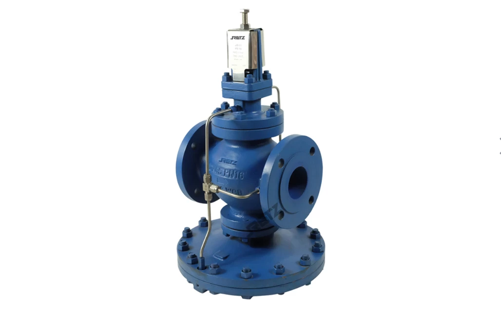
2. Pressure Relief Valve Troubleshooting Methods
(1) Unstable Pressure Fluctuations
Fault Analysis:
a). Air mixed into the hydraulic fluid.
b). Damping hole occasionally clogged.
c). The roundness of the spool and valve body bore exceeds the specified tolerance, causing the valve to stick.
d). The spring is deformed or stuck in the spool, making spool movement difficult, or the spring is too soft.
e). The steel ball is not perfectly round, the steel ball and valve seat do not fit well, or the conical valve is installed incorrectly.
Troubleshooting Methods:
a).Eliminate air in the oil.
b). Clean the damping hole.
c).Repair and grind the valve hole and sliding valve.
d).Replace the spring.
e).Replace the steel ball or disassemble the cone valve for adjustment.
(2) The secondary pressure does not rise sufficiently
Fault analysis:
a).External leakage.
b).Poor contact between the cone valve and the valve seat.
Elimination method:
a).Replace the seals, tighten the screws, and ensure even torque.
b).Repair or replace.
(3) Does not reduce pressure
Fault analysis:
a).The oil drain port is blocked; the drain pipe is connected to the return pipe, and there is return pressure.
b).The main valve spool is stuck in the fully open position.
Elimination method:
a).The oil drain pipe must be separated from the return pipe and return to the oil tank independently.
b).Repair or replace parts. Check the oil quality.
3.Pressure Relief Valve Maintenance
From a macro perspective, property management and maintenance personnel should first familiarize themselves with the general overview and types of water supply systems in high-rise buildings. They must understand the performance characteristics of various domestic water supply systems, firefighting systems, and even complex production water supply systems. A basic comprehension of the hydraulic balance operation mechanisms, technical configurations, and particularly the principles of various pressure-reducing components within the system, as well as their performance requirements, is essential.
It is crucial to understand the system's normal performance indicators. When faults occur—such as unstable or rapidly fluctuating pressure in some water-using equipment, the presence of negative pressure suction, or intermittent whistling noises in critical pressure-reducing sections of the system—personnel should be able to analyze and diagnose the causes rationally. This enables them to guide practical operations with the correct approach.
At the same time, there is a need to strengthen the sense of responsibility in maintenance management, enhance professional technical skills, and develop hands-on abilities for system debugging, operation, and emergency troubleshooting. Proper management of water supply and usage facilities in every high-rise building ensures that owners (or users) benefit from reliable service.
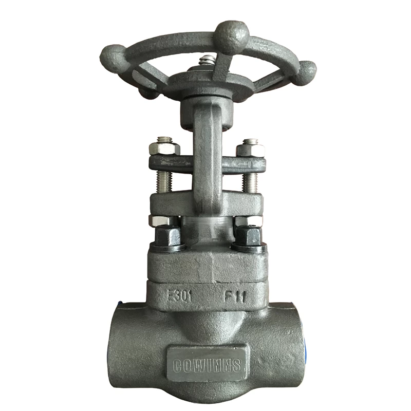
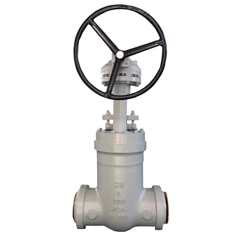
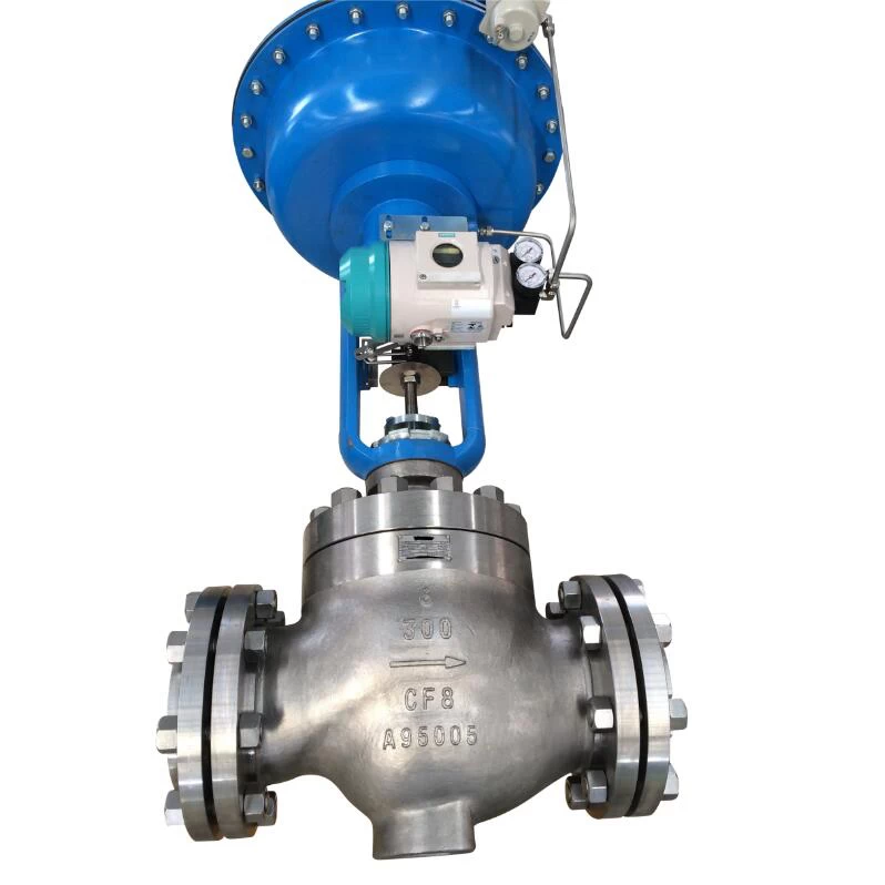
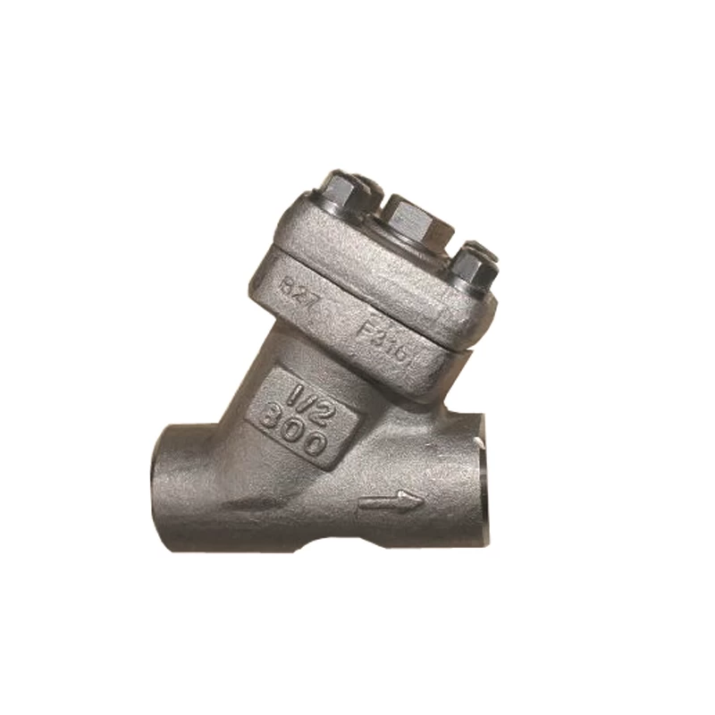
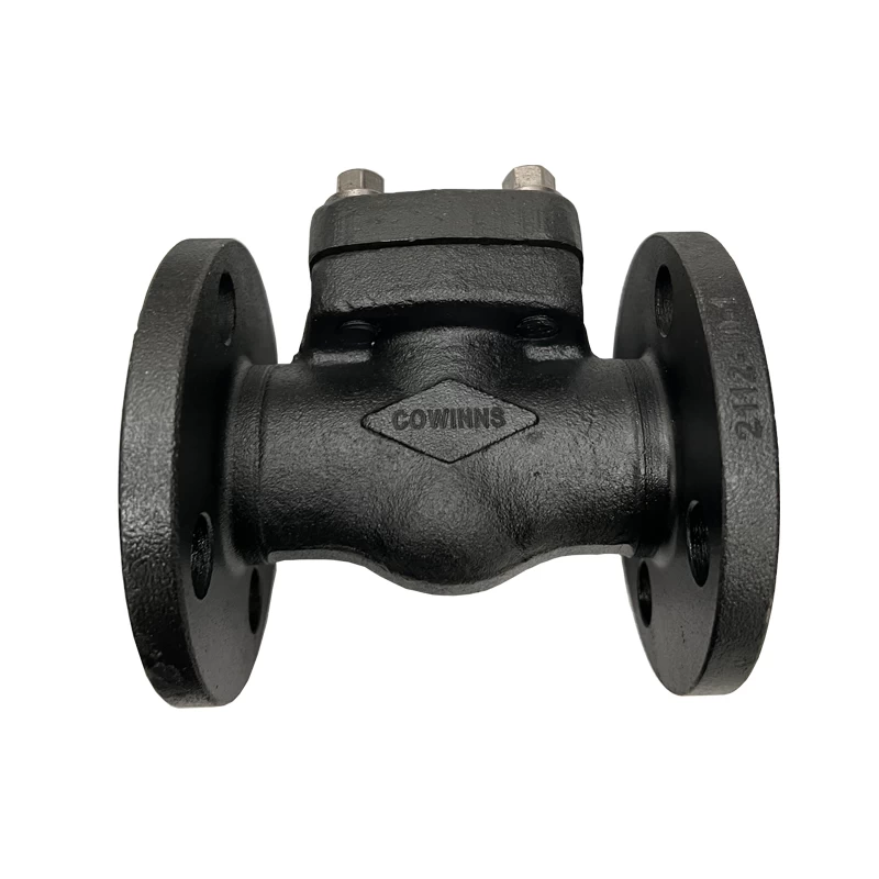
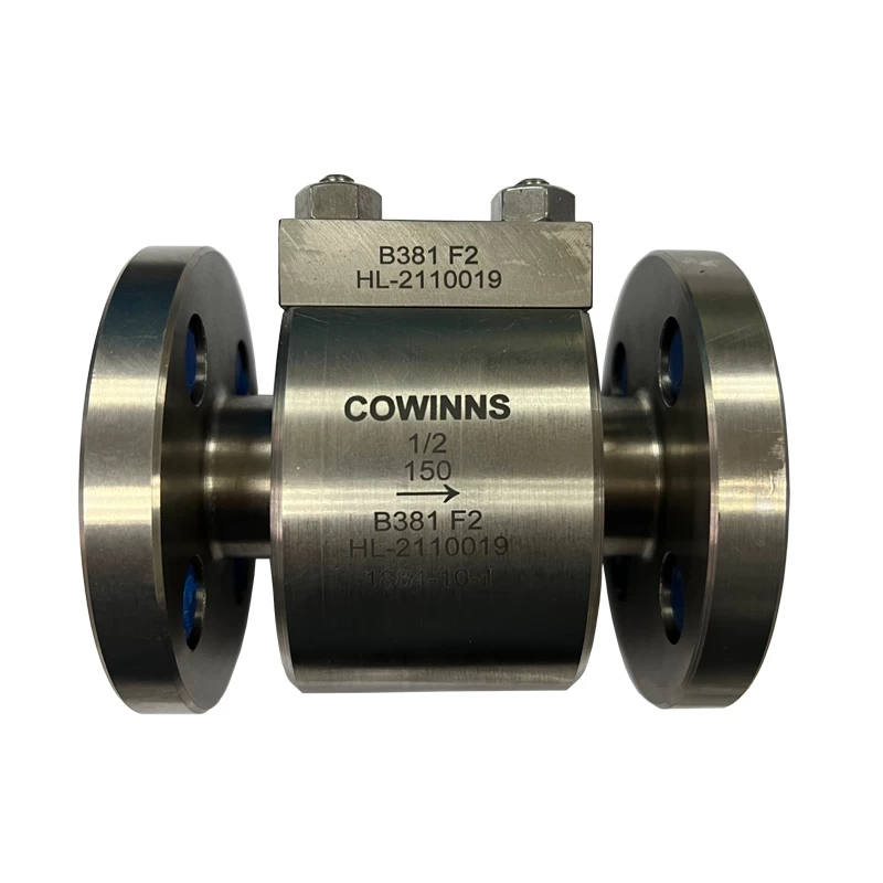
Pressure relief valves can be used for wide application ,for special chemical pipeline cowinns has experience of special alloy valves such as titanium check valve and so on.
 +86 512 68781993